
Implantable antenna

a technology of connectors and antennas, applied in the direction of antennas, electric signalling details, electromagnetics, etc., can solve the problems of difficult or impossible time-consuming, labor-intensive and specialized crafts, and often labor-intensive manufacturing of wiring and connector components, and achieve the effects of increasing manufacturing throughput, reducing labor costs, and reducing labor costs

Inactive Publication Date: 2011-05-31
COCHLEAR LIMITED
View PDF52 Cites 12 Cited by
  • Summary
  • Abstract
  • Description
  • Claims
  • Application Information

AI Technical Summary

Benefits of technology

The formed antenna can comprise a receiver antenna. The method has potential advantages in providing a relatively efficient and inexpensive process of antenna manufacture, particularly assembly of receiver antennae for implantable tissue-stimulating devices, such as cochlear implants. The present invention further provides a method of forming an antenna that can allow the manufacturing process to become automated or semi-automated so providing a desirable alternative to current manufacturing processes which require, extensive labor input and increased manufacturing throughput.
The non-linear path of said portion of the wire provides a degree of flexibility to the wire following implantation. For example, the nonlinear path can be adapted to compensate for any movement between the housing and the one or more electrodes, such as movement which may occur naturally due to body growth.
In a preferred embodiment, the device formed by the method according to the fifth aspect is preferably an electrode array for an electrode assembly. The method has potential advantages in providing a relatively efficient and inexpensive process of electrode assembly manufacture, particularly assembly of intracochlear electrode assemblies. The present invention further provides a method of forming an electrode array for an electrode assembly that preferably allows the manufacturing process to become automated or semi-automated so providing a desirable alternative to current manufacturing processes which require extensive labor input and increased manufacturing throughput.

Problems solved by technology

In many electrical devices, particularly those that are manufactured on a very small scale, the manufacture of the wiring and connector components is often a labor intensive and specialized craft.
Ensuring that the wiring and connection of the various components of the systems occurs correctly is often the most expensive and labor intensive aspect of the manufacturing process, resulting in large costs associated with the time taken to manufacture the device which is often passed on to the ultimate consumer.
This is also the case when such devices need to be specifically hand-made to a specification as often he availability of the device is dependent upon the time taken to manufacture the device, with the time taken being difficult or impossible to expedite.
As such, manufacturing such devices to ensure that they are reliable and sturdy is a specialized art, and requires much time and expense.
Current techniques for the manufacture of electrode arrays for cochlear implant systems, in particular, are relatively highly labor intensive.
This is in the main due to the intricate nature of the array and the very small dimensions of the array necessary to allow it to be inserted in the scala tympani of the human cochlea.

Method used


Image

  • Implantable antenna
  • Implantable antenna
  • Implantable antenna

Examples


Embodiment Construction

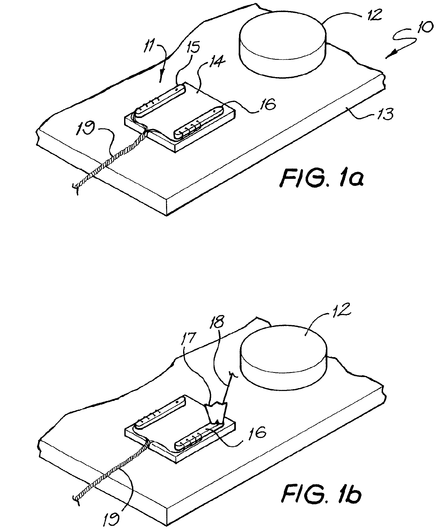
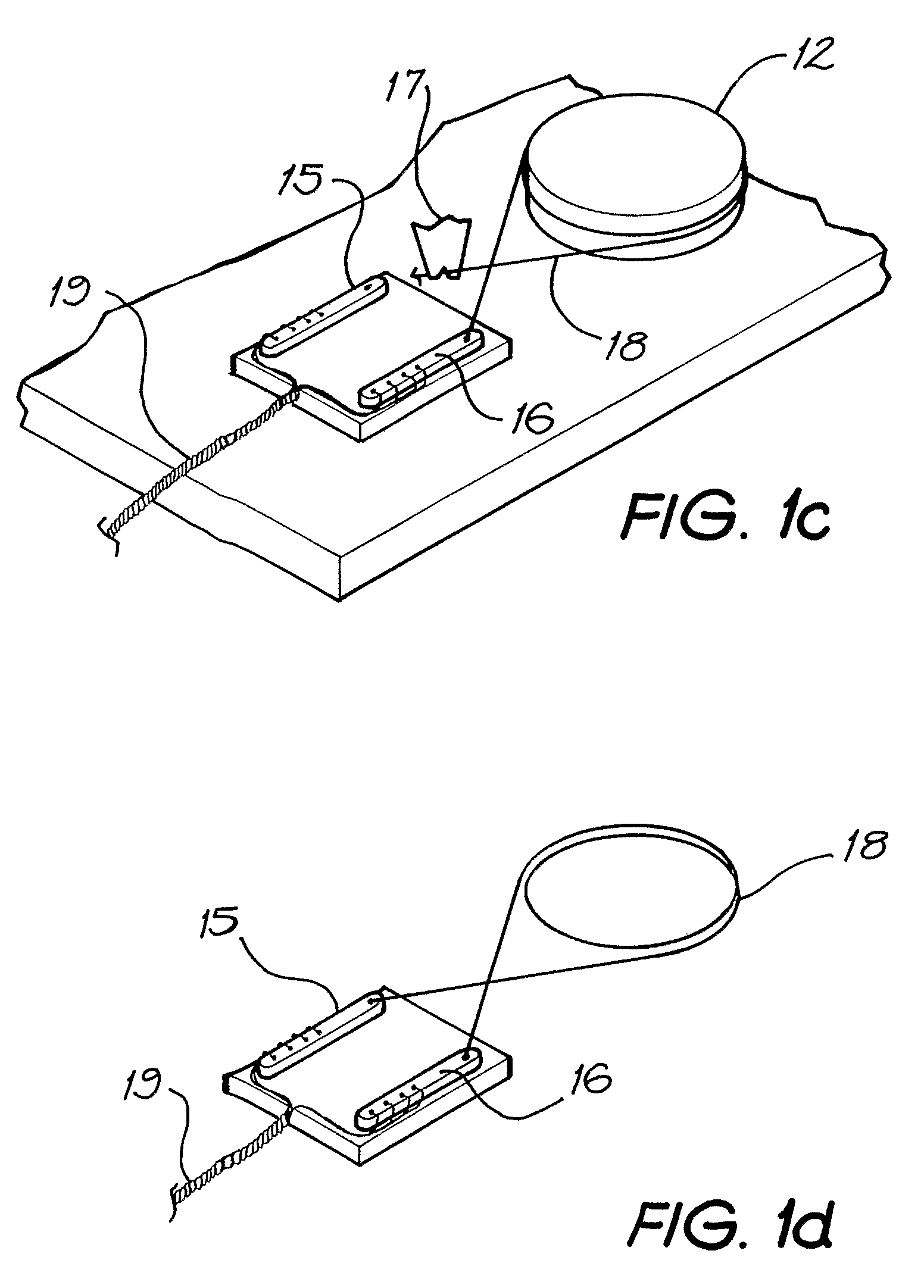
FIG. 1 depicts some of the steps of a method according to the present invention, depicted generally as 10, for forming an antenna and feed through assembly that is suitable for use in a tissue-stimulating device, such as a Cochlear™ implant (also referred to as Cochlear™ prostheses, Cochlear™ devices, and the like; for simplicity hereinafter referred to as “cochlear implant”).

As depicted in FIG. 1a, a feedthrough member 11 and an antenna template 12 are mounted to a workspace member 13. The relative position of the member 11 and template 12 are based on the desired dimensions of the antenna to be formed.

In the depicted embodiment the feedthrough member 11 is mountable in a wall or chassis of a housing 14 and comprises a fist portion 15 and a second portion 16, Both of the portions 15,16 have a plurality of conductive posts extending through an electrically insulating block that hermetically seals the housing 14. In the depicted embodiment, the feedthrough member 11 is usable for bot...


PUM

PropertyMeasurementUnit
thicknessaaaaaaaaaa
thicknessaaaaaaaaaa
thicknessaaaaaaaaaa

Abstract

A method of forming and connecting an antenna to a feedthrough member of a housing. The method comprising a step of: positioning the feedthrough member and an antenna template relative to each other. A step of connecting the first portion of at least one electrically conducting wire to the feedthrough member. An additional step of winding the wire at least once around the antenna template, and a further step of connecting a second portion of each wire to said feedthrough member.

Description

CROSS-REFERENCE TO RELATED APPLICATIONSThe present application claims priority from Provisional Patent Application Nos 2003906787 and 2004905355 filed on 8 Dec. 2003 and 16 Sep. 2004, respectively, the contents of which are incorporated herein by reference.FIELD OF INVENTIONThe present invention relates generally to the field of forming miniature wiring and connector systems for electrical products, and more specifically, for forming miniature wiring and connective systems for a medical implant such as a cochlear implant assembly.BACKGROUND OF THE INVENTIONIn many electrical devices, particularly those that are manufactured on a very small scale, the manufacture of the wiring and connector components is often a labor intensive and specialized craft. Ensuring that the wiring and connection of the various components of the systems occurs correctly is often the most expensive and labor intensive aspect of the manufacturing process, resulting in large costs associated with the time take...

Claims


Application Information

Patent Timeline
Patent Type & Authority Patents(United States)
IPC IPC(8): H01P11/00H01Q1/36H01Q7/00
CPCH01Q1/36H01Q7/00Y10T29/49018Y10T29/49117Y10T29/49002Y10T29/49016Y10T29/49071
Inventor HO, ANDYEDER, NIKIWALKER, DAVIDMEAGHER, KATHERINESCHULLER, PETER
Owner COCHLEAR LIMITED
Learn More