High performance, low emission engines, multiple cylinder engines and operating methods

a technology of high performance and low emission, which is applied in the direction of combustion engines, charge feed systems, electric control, etc., can solve the problems of high hydrocarbon content in diesel exhaust, damage to the engine, and unburned hydrocarbons

Active Publication Date: 2011-06-07
STURMAN DIGITAL SYST
View PDF136 Cites 48 Cited by
  • Summary
  • Abstract
  • Description
  • Claims
  • Application Information

AI Technical Summary

Problems solved by technology

The unburned hydrocarbons in a diesel engine exhaust, on the other hand, generally have two primary causes, namely first, the impingement of part of the spray of injected fuel on a relatively cool surface before the fuel has an opportunity to burn, or at least entirely burn, and second, the local injection of fuel into regions of the combustion chamber having inadequate oxygen to locally allow all of the injected fuel to burn.
When the piston is in its uppermost position, or near its uppermost position, the injection spray should not be downward onto the top of the piston, as that causes a high content of hydrocarbons in the diesel exhaust, as previously descr

Method used


Image

  • High performance, low emission engines, multiple cylinder engines and operating methods
  • High performance, low emission engines, multiple cylinder engines and operating methods
  • High performance, low emission engines, multiple cylinder engines and operating methods

Examples


Embodiment Construction

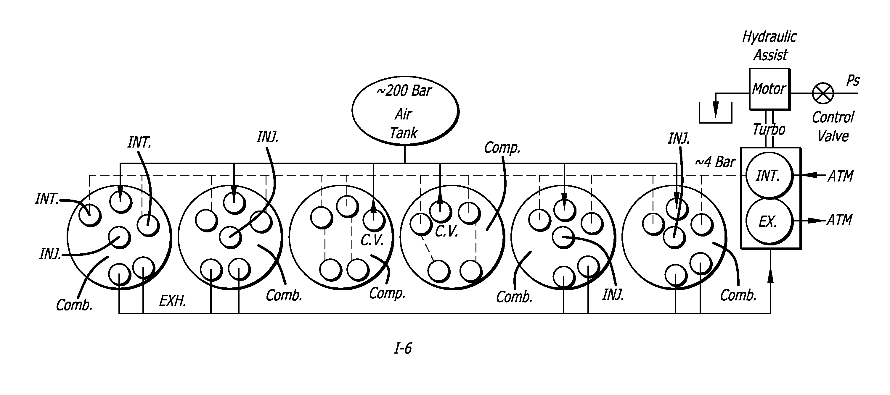
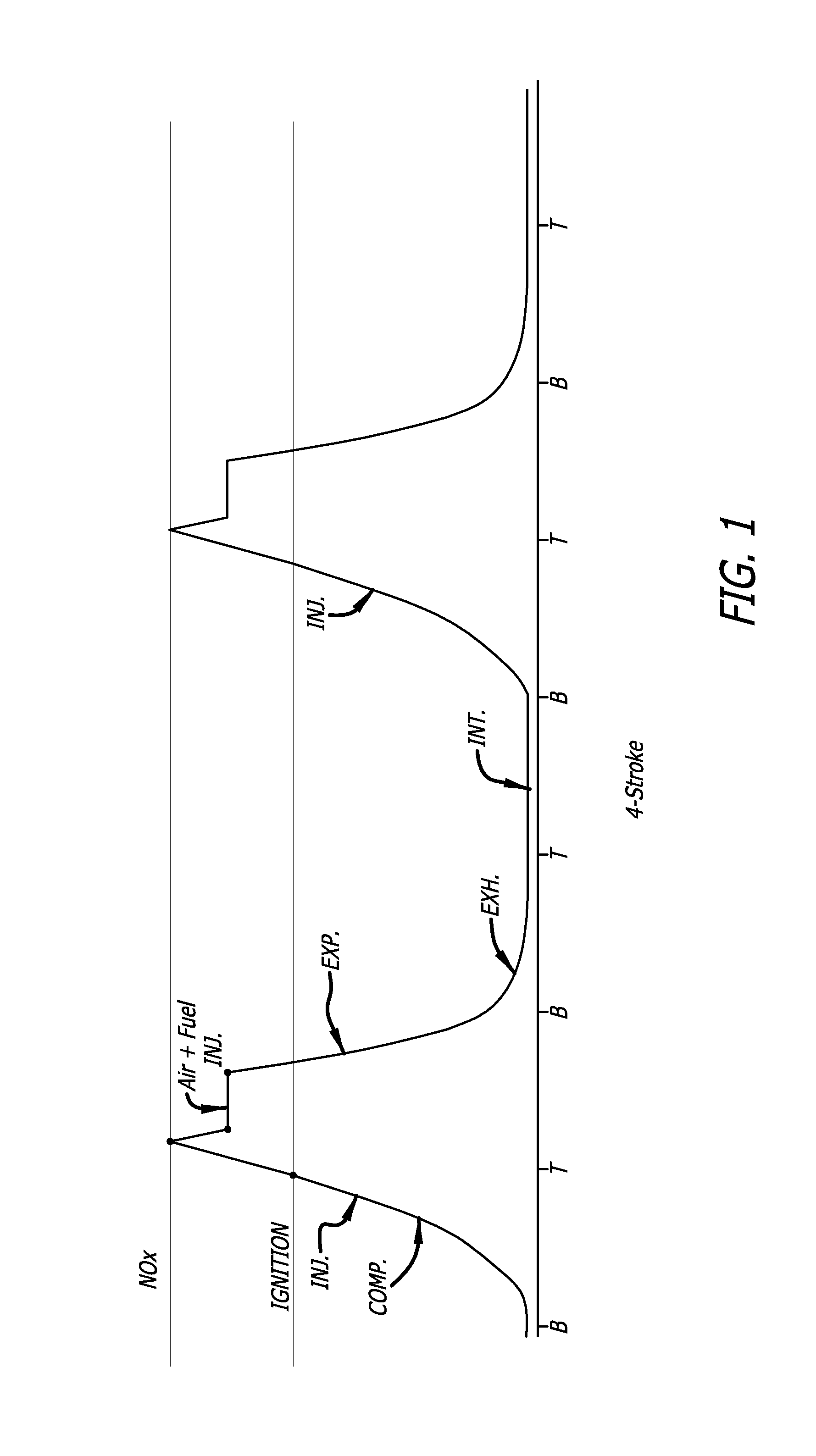
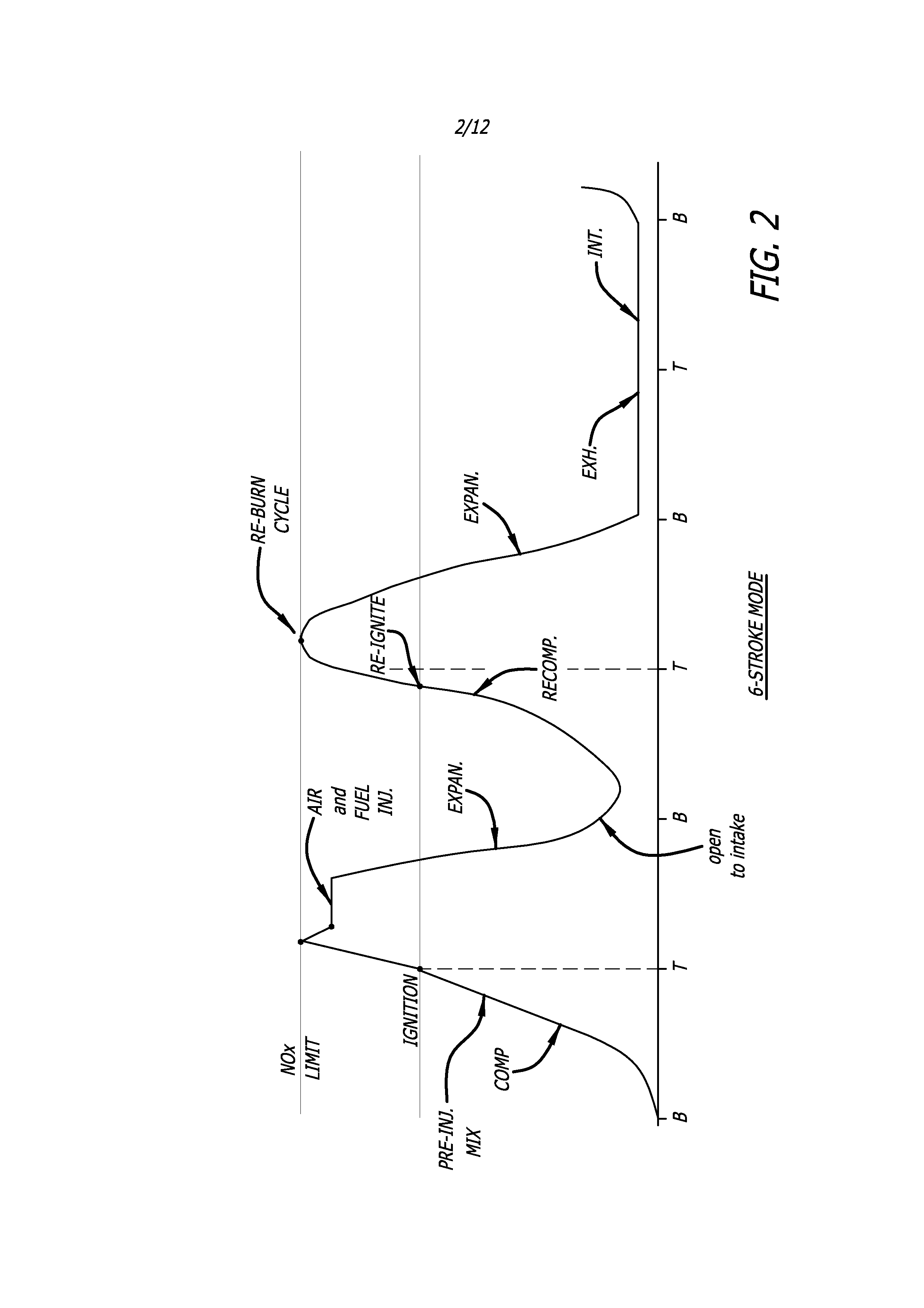
[0023]In one embodiment of the invention, both fuel and air are injected into the combustion chamber during at least some of the main injection of fuel. The air is preferably injected into the region surrounding the fuel injector tip so that a fresh supply of oxygen rich air is provided during main injection, even as the piston moves away from the injector, and thus the center of the remaining previously available air, so to speak, also moves away from the injector. This can provide more complete combustion of the fuel injected during main injection and can further allow the injection and combustion of greater amounts of fuel over the same or a greater crankshaft angle, thereby increasing the energy output of that combustion cycle. Further, by careful control of the air, and particularly the fuel injected during pre-injection and main injection, combustion temperatures may be kept below the nitrous oxide formation temperature limit.

[0024]One convenient way of achieving this is by se...


PUM


Abstract

High performance, low emission engines, multiple cylinder engines and operating methods based on compression ignition of a combustion chamber charge. In accordance with the methods, fuel is injected into the combustion chamber after the exhaust valve closes, and air is injected into the combustion cylinder before the end of the compression stroke in an amount to limit the temperature after ignition to less than the temperature at which NOX forms. After ignition and during the power stroke, more air is injected into the combustion chamber to sustain combustion until all fuel is consumed, the air being injected so as to again limit the combustion temperatures to less than the temperature at which NOX forms. The air injected during the compression stroke is injected at substantially the same combustion chamber pressure as the air injected during the power stroke, so that air may efficiently be injected from the same pressurized source. The fuel injected into the combustion chamber may be all the fuel needed, or additional fuel may be injected during the power stoke.

Description

CROSS-REFERENCE TO RELATED APPLICATION[0001]This application claims the benefit of U.S. Provisional Patent Application No. 60 / 982,353 filed Oct. 24, 2007.BACKGROUND OF THE INVENTION[0002]1. Field of the Invention[0003]The present invention relates to the field of internal combustion engines such as diesel engines, gasoline engines and engines designed to operate on alternate fuels.[0004]2. Prior Art[0005]The present invention is applicable to various types of engines, including diesel engines, gasoline engines and engines intended to operate on alternate fuels. However for purposes of specificity in the disclosure herein, preferred embodiments will first be described with respect to diesel engines, after which the applicability to other types of engines will be described. Accordingly, the prior art with respect to diesel engines will be described herein, it being understood that generally speaking, many of the characteristics of diesel engines described herein translate in various w...

Claims


Application Information

Patent Timeline
IPC IPC(8): F02M23/04
CPCF02D13/02F02D13/0253F02D13/0265F02D13/0276F02D35/023F02D41/0087F02M23/04Y02T10/18F02D2041/001F02D2041/3088F02D2250/36Y02T10/146F02D35/026F02D41/403Y02T10/12
Inventor STURMAN, ODED EDDIE
Owner STURMAN DIGITAL SYST
Why Eureka
Try Eureka