Multiple application purification and recycling device

a technology of purification device and recycling device, which is applied in the direction of vacuum distillation separation, filtration separation, separation process, etc., can solve the problems of limiting the usefulness of water distillation units currently in use, requiring inconvenient positioning, and bulky water distillation units. , to achieve the effect of simplifying the construction, improving the distillation process, and universal us

Inactive Publication Date: 2011-06-07
MANSUR CORP
View PDF30 Cites 10 Cited by
  • Summary
  • Abstract
  • Description
  • Claims
  • Application Information

AI Technical Summary

Benefits of technology

[0006]In view of the limitations now present in the prior art, the present invention provides a new and useful water and diverse fluids purification device utilizing an enhanced distillation process that is simpler in construction, more universally usable, and more versatile in operation than known apparatus of this kind.
[0007]The present invention efficiently and effectively purifies water and a variety of other fluids (such as tap water, ocean water, pond water, stream water, river water, street runoff, and industrial waste water, for example) using an enhanced distillation process that can readily be adaptable and scalable for multiple applications. The device according to the invention is a liquid distillation device that can be used, in particular, to produce distilled drinking water in a compact system for low cost. The purification device of the invention overcomes all of the above-described disadvantages of water purification equipment in current use: (i) it is compact and self contained; (ii) it is easy to use; (iii) it is self monitoring; (iv) it automatically self cleans; and (v) it is energy efficient. A valve, in particular, a ceramic valve, is precisely timed and has sensors that automatically control a sequence of functions for providing the pure liquid and for carrying out the automatic self-maintenance functions. The device can connect to a tap water source in households or businesses and automatically and economically creates pure, chilled or heated distilled water for dispensing on-demand and automatically maintains a set schedule to wash the distillation chamber. A liquid dispensing unit can be used for supplying the liquid to be purified to the distillation chamber, the liquid dispensing unit being selectively connected automatically and repetitively to the distillation chamber by a valve to dispense a pre-set amount of the liquid to the distillation chamber. Moreover, any of a variety of flavor agents and / or health benefiting minerals and vitamins may be added to the pure distilled water.
[0008]For efficiently heating the liquid in the distillation chamber, a large surface area contact chamber, within a highly efficient micro design, to effectively maximize heat generation, a 25% reduction in power consumption results in the production of purified water for about 1 cent per 8 ounce glass. Scale and contaminant build up inside the boiling chamber is cleaned with a rotating paddle / auger / brush that completely and automatically wipes and polishes the distillation chamber during every cycle. There is virtually no build-up on the chamber walls and contaminants are automatically and forcefully discharged down a drain. Significantly, the purification device can be scaled in size to accommodate any application. For example, the device can be sized to fit inside a vending machine, for example, a school cafeteria, to replace the soda machines currently accessed by 53 million grammar and high school students daily. With the addition of flavoring agents, the device can be used to provide students with the purest and healthiest beverage in the world, for approximately 1 cent a glass. In military applications, the device can be increased in size to produce large quantities of the purest water near a battlefield, natural disaster area, or for humanitarian relief efforts because it can use any available source of water including oceans, rivers, ponds, streams, pools, and, even, stagnant pools. The device can be utilized to purify machine tool coolants and significantly minimize disposal costs, to purify industrial drain traps and eliminate pumping services, and / or to purify any water-based waste hazardous stream generated by a commercial development.

Problems solved by technology

Water distillation units in current use have several shortcomings that limit their usefulness as a practical and desirable way for providing pure water, particularly in a household environment.
For instance, water distillation units currently in use are usually bulky and are often designed to require inconvenient and unsightly positioning on countertops.
These deposits adversely affect the function of many of the components, including the heating element, and limit the overall cleanliness of the unit.
The intensive labor for removing these contaminants requires manual disassembly of the unit and separation of parts, which are then soaked in certain chemicals, such as citric acid.
The chemicals react with the deposits, eventually causing them to dissolve and separate from the surface of the soaked parts.
The production of truly pure distilled water can be problematic, and many water distillers in current use are not entirely effective in removing all the contaminants.
However, activated carbon filter media becomes saturated in time and must be monitored, maintained, and manually replaced on a regular basis.
A further drawback associated with water distillation units in current use is the significant amount of energy required to heat and vaporize water in the distillation process and poor energy efficiency.
Furthermore, water in its purest state typically has a neutral or bland taste because it lacks the flavor of the minerals found in water that most people are accustomed to drinking.
These flavor-producing minerals are removed by distillation leaving the pure water with a taste that does not appeal to most consumers.

Method used


Image

  • Multiple application purification and recycling device
  • Multiple application purification and recycling device
  • Multiple application purification and recycling device

Examples


Embodiment Construction

[0063]In the figures of the drawings, unless stated otherwise, identical reference symbols denote identical parts.

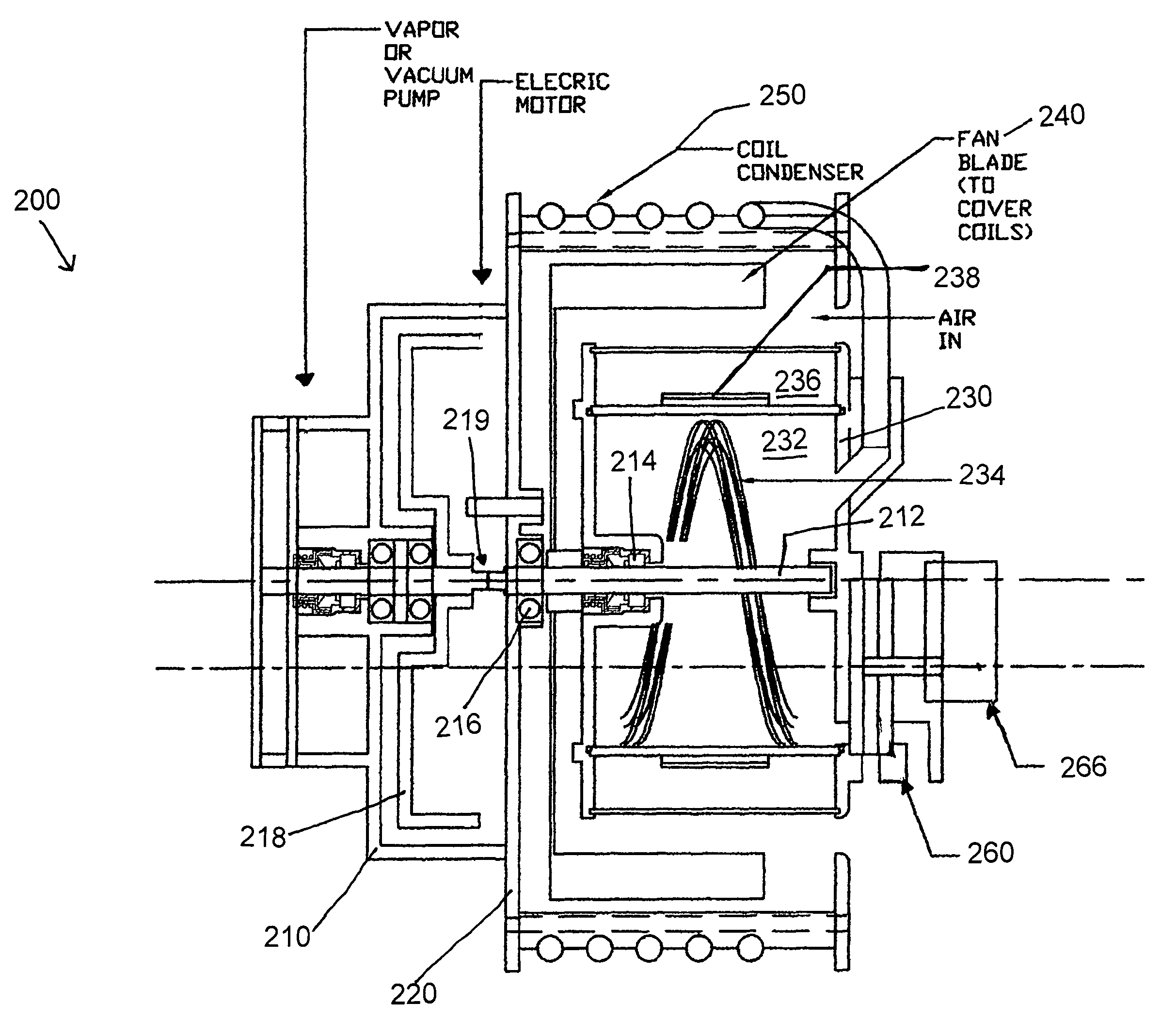
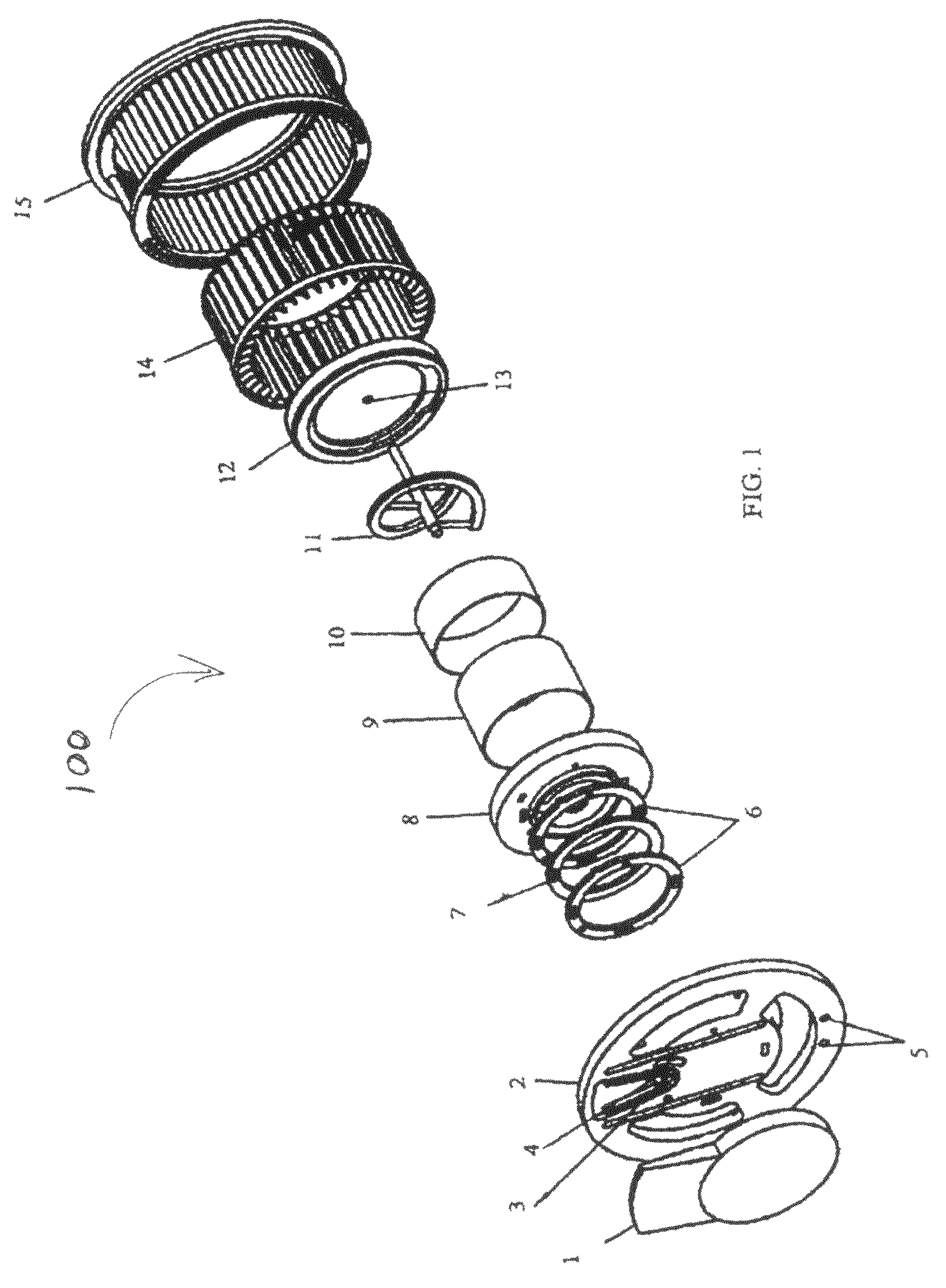
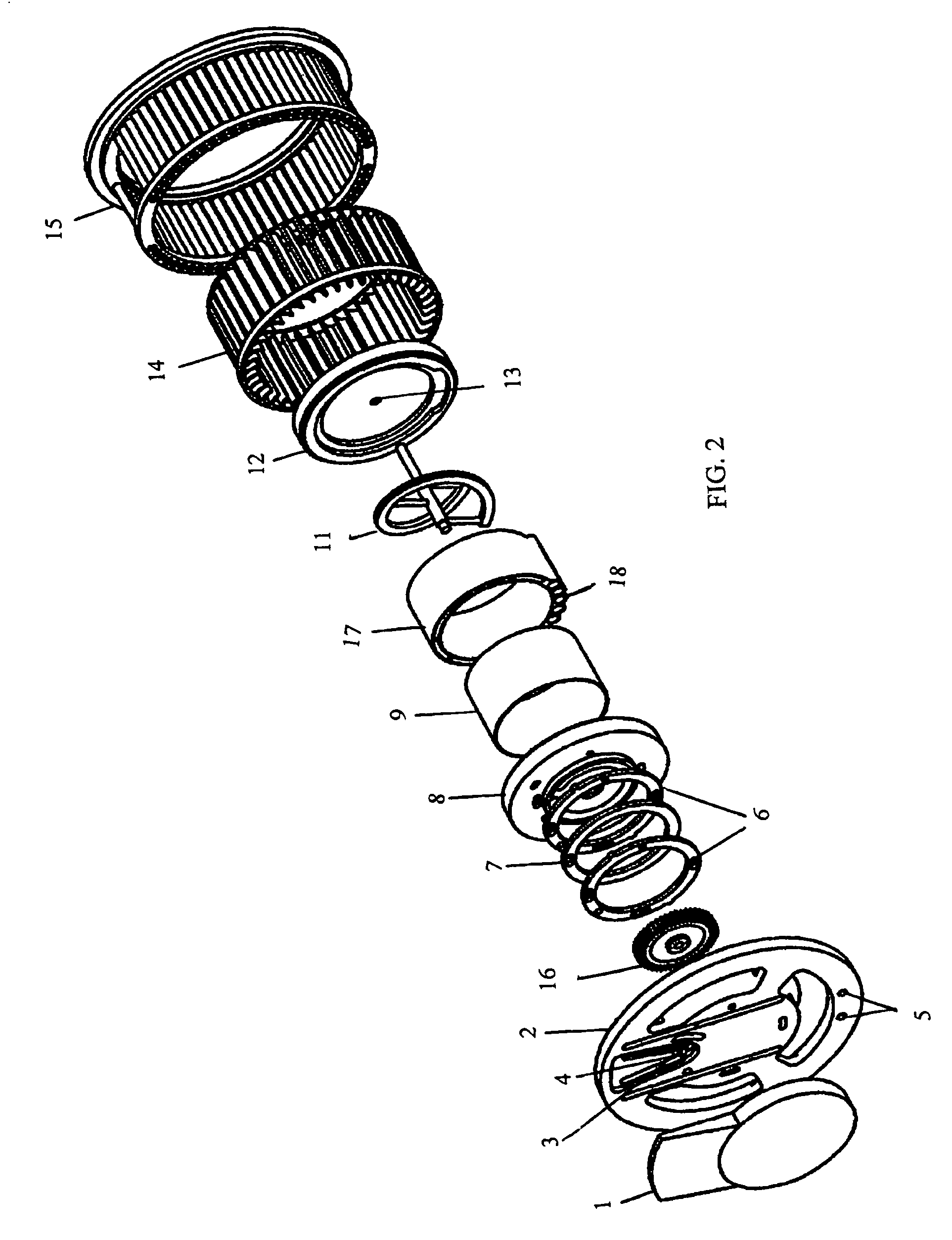
[0064]FIGS. 1 to 7 illustrate a first embodiment of a multiple application purification and recycling device according to the present invention with a horizontally oriented, fixed, cylindrical distillation chamber forming the core of the coaxial distillation device. The distillation chamber incorporates a multi-function mechanical rotating device that produces a thin film coating, cleans, and positively directs all contaminants out of the chamber. The exterior of the cylindrical chamber is peripherally surrounded by a controlled heat-generating source. The steps of inflow, heating, purging vapors, boiling, distillation exit, rinse entry, cleaning, and waste elimination (not necessarily listed in order) are controlled by a valve. The valve can be a rotating valve and can also be coaxial with the distillation chamber. A centrifugal blower wheel is coaxially located between...


PUM

PropertyMeasurementUnit
volumeaaaaaaaaaa
diameteraaaaaaaaaa
diameteraaaaaaaaaa

Abstract

A multiple application recycling and purification device has a coaxial core that is horizontally oriented, non-rotating, cylindrical distillation chamber. The enhanced, completely coaxial configuration continuously cleans the entire distillation chamber and spreads a thin film of liquid to enhance distillation and positively aid in the removal of remaining contaminants. Through a timed and positioned valve, the device removes and purges lower-temperature contaminants. Timed valves and sensors control all phases of the distillation to provide a coaxially integrated, stand-alone, adaptable, scalable and maintenance free distillation unit that self-monitors, self-cleans and economically functions to produce the pure distilled liquid, e.g., water. This device can be modified to purify any numerous array of liquids and can be scaled to produce any amount of purified liquids for either household, commercial, or industrial applications.

Description

CROSS-REFERENCE TO RELATED APPLICATION[0001]This application claims the benefit under 35 U.S.C. §119(e) of U.S. Provisional Application No. 60 / 760,849, filed Jan. 20, 2006, the complete disclosure of which is hereby incorporated by reference herein in its entirety.STATEMENT REGARDING FEDERALLY SPONSORED RESEARCH OR DEVELOPMENT[0002]n / aFIELD OF THE INVENTION[0003]The present invention lies in the field of liquid purification systems, in particular, to liquid distillation systems.BACKGROUND OF THE INVENTION[0004]The process of distillation is well known and is regarded as the most effective way to separate toxins, bacteria, chemicals and solids from liquids (such as tap water) to produce a pure liquid (e.g., drinking water). In the past, various water distillation units have been developed to purify tap water in both household and commercial applications. The primary function of these water distillation units is to heat water and condense the resultant vapors in order to separate and ...

Claims


Application Information

Patent Timeline
Patent Type & Authority Patents(United States)
IPC IPC(8): B01D1/22B01D3/08B01D1/28B01D3/10B01D3/42
CPCB01D1/0017B01D1/222B01D3/08C02F1/18B01D5/0006B01D5/006C02F1/08B01D3/12Y10S159/16
Inventor MANSUR, PIERRE G.
Owner MANSUR CORP
Why Eureka
Try Eureka