Solar cell module and solar cell array

a solar cell and solar panel technology, applied in the direction of solar heat collector mounting/support, solar heat collector safety, light and heating apparatus, etc., can solve the problems of solar panel electrical output dramatically dropping, sunlight blocking, etc., to achieve sufficient hydrophilicity, improve disposability of liquid, and reduce power output

Active Publication Date: 2011-06-07
KYOCERA CORP
View PDF21 Cites 35 Cited by
  • Summary
  • Abstract
  • Description
  • Claims
  • Application Information

AI Technical Summary

Benefits of technology

[0019]A solar cell module according to claim 1 of the present invention comprises a solar cell panel configured by arranging a solar cell element between a light receiving surface side member and a rear surface side member, and a module frame fixed to the solar cell panel surrounds the solar cell panel with its interior surface being abutted with an external peripheral part of the light receiving surface side member, wherein the module frame has a notch that extends from its inner part towards its external part in plan view from a side of the light receiving surface side member and is provided with an end portion on an exterior side surface of the module frame, and the notch has a draw part with smallest width at an inner part rather than at the end portion, therefore the liquid existing on the light receiving surface of the solar cell module is smoothly moved and discharged to the outside of the solar cell module by passing though the draw part of the notch. Accordingly, cases will be reduced where the dirt and dust contained in the liquid is left after the liquid remaining on the light receiving surface evaporates, which is a cause of the decrease in power output. Here, the exterior surface of the module frame is a concept indicating a part from the side surface of the solar cell panel to the side surface of the solar cell module (i.e. the thickness part of the module frame).
[0020]A solar cell module according to claim 2 of the present invention is the solar cell module according to claim 1, wherein a width of the draw part is from 2 mm to 15 mm and a difference between the width of the draw part and a width of the end portion is from 1 mm to 7 mm. In this manner, the liquid is smoothly discharged to outside as well as controlling the accumulation of the liquid at the draw part. It is assumed that this effect is obtained because sufficient hydrophilicity is ensured at the inner surface of the notch. Especially, by making the difference between the width of the draw part and the end portion from 1 mm to 7 mm, the liquid existing on the light receiving surface of the solar cell module can be discharged to the outside more effectively.
[0021]Further, a solar cell module according to claim 3 of the present invention is the solar cell module according to claim 1 or 2, and because it is configured to have a protruding portion on at least a part of its exterior side surface, when the solar cell module is set next to another solar cell module, it plays a role as a cushioning material against the member adjacent to the protruding portion. Also, by forming a predetermined space between the solar cell modules adjacent to each other, it is possible to improve the disposability of the liquid to the rear surface side of the solar cell module.
[0022]According to a solar cell array according to claim 4 of the present invention, because the end portions of the notches are aligned at a position corresponding to each other, the liquid existing on the light receiving surface of one solar cell module increases its flow rate and total amount as the liquid moves to the light receiving surface of the adjacent solar cell panel through the notch of each solar cell module, therefore dust and dirt are taken into the liquid effectively and are discharged to the outside of the solar cell array.
[0023]A solar cell array according to claim 5 of the present invention is the solar cell array according to claim 4, and because the solar cell modules adjacent to each other are fixed to each other by a interlock portion provided to their module frames, the aforementioned end portions of the notches can easily be aligned. In addition, because the module frame can be set to another without fixing it to a base and the like, the number of working hours required for setting and the necessary members such as bolts and nuts can be reduced.

Problems solved by technology

The liquid that remains in this way subsequently evaporates leaving the dust and so on that were contained in the liquid on the light receiving surface of the solar cell module, thus creating a problem where sunlight is blocked and the electrical output of the solar cell module dramatically drops.

Method used


Image

  • Solar cell module and solar cell array
  • Solar cell module and solar cell array
  • Solar cell module and solar cell array

Examples


first embodiment

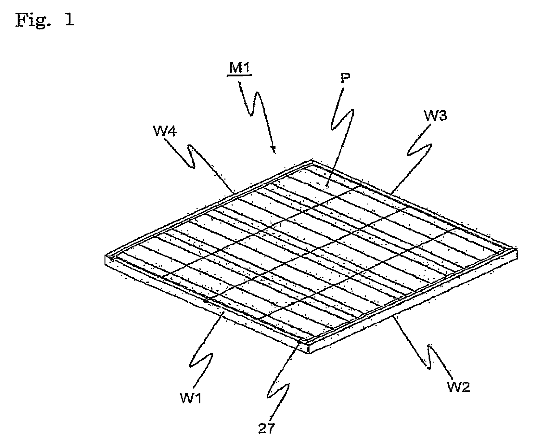
[0095]FIG. 1 is an external perspective view of a solar cell module according to a first embodiment of the present invention.

[0096]A solar cell module M1 comprises solar cell panel P and four module frames W1 to W4 which are mounted to the external peripheral part of this solar cell panel P.

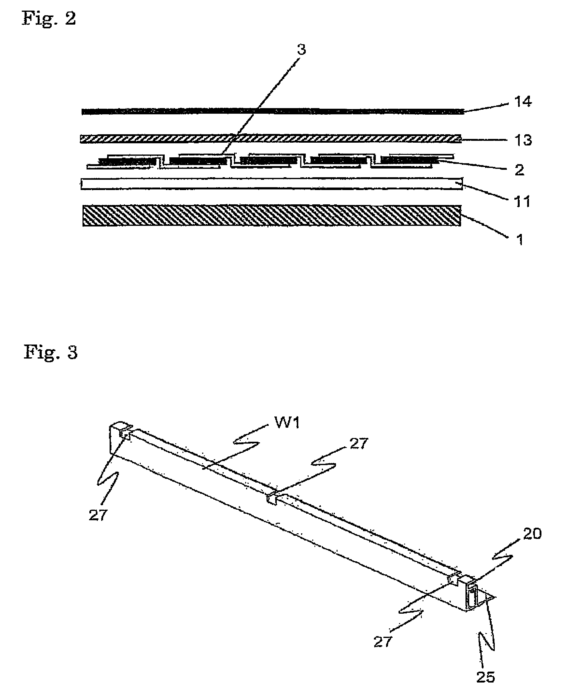
[0097]First, the solar cell panel P will be explained with reference to FIG. 2.

[0098]The solar cell panel P comprises a light receiving surface side member 1 that is a light-transmissive substrate, a light receiving surface side sealer 11, a solar cell element 2, a rear surface side sealer 13 and a rear surface side member 14 that is the rear surface sealer. Note that each solar cell element is electrically connected by a connection tab 3. Each structure will be explained in detail below.

[0099]A substrate that is comprised of a glass or a polycarbonate resin is used for the light receiving surface side member 1. Examples of the glass may be a white plate glass, tempered glass, double-tempered gla...

second embodiment

[0146]A solar cell module according to a second embodiment of the present invention will be explained with reference to FIGS. 11 to 19. Note that the same configurations as those of the first embodiment are assigned the same reference numerals and the explanation therefor is omitted. Characteristic parts of the present embodiment will mainly be explained below.

[0147]FIG. 11 is an external perspective view of a solar cell module M2 according to a second embodiment of the present invention.

[0148]A plurality of the notches 27 similar to that in the aforementioned embodiment are provided to a module frame W5 of the solar cell module M2 at its both ends and at the center. By providing a notch group 33 comprising a plurality of notches 27 at the both ends and the center of the module frame W5, the liquid during or after rain can be smoothly discharged even for a large-sized solar cell module such as the solar cell module M1 with each side exceeding 70 cm, thus dirt is less likely to remai...

third embodiment

[0158]A solar cell module according to the third embodiment of the present invention will be explained with reference to FIGS. 20 to 25.

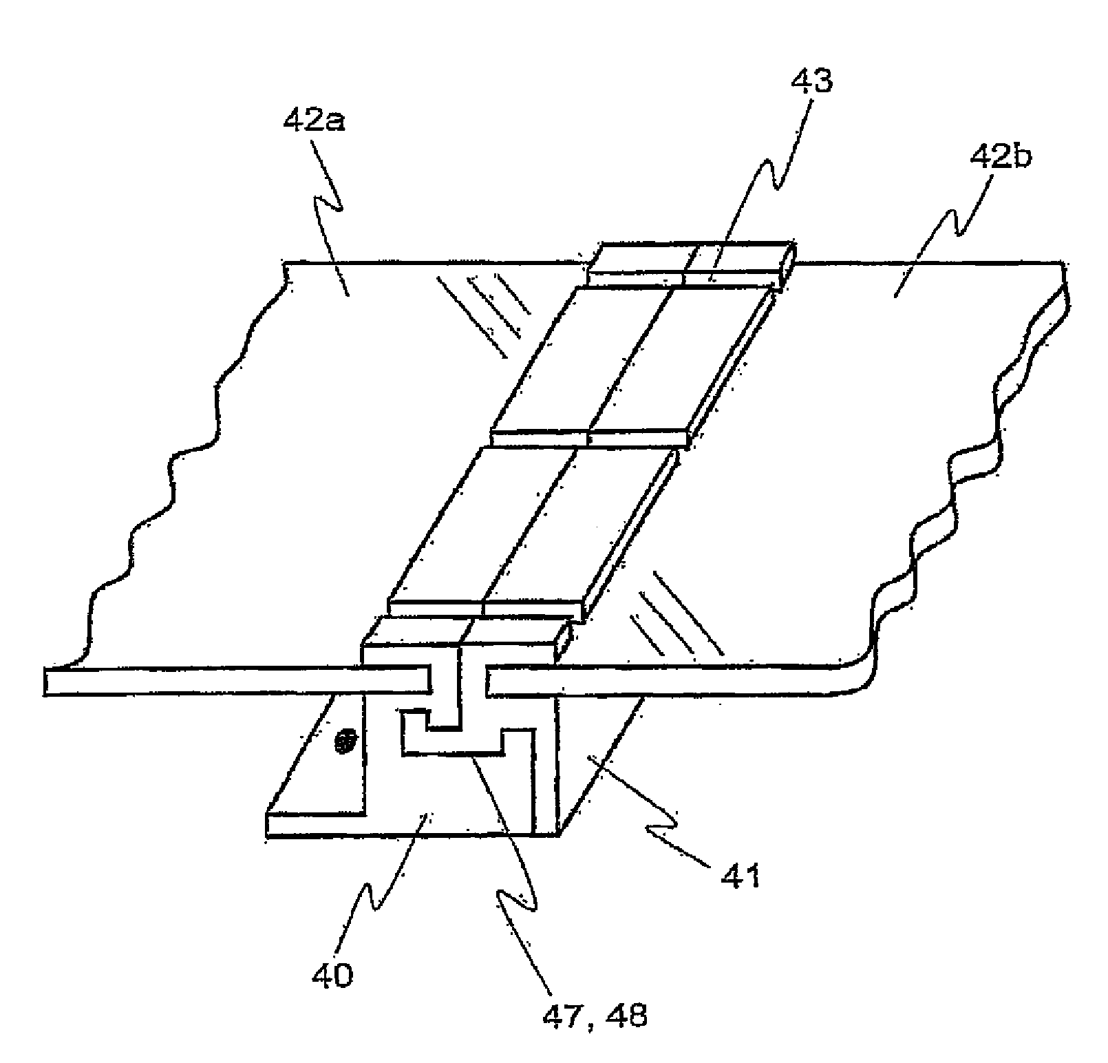
[0159]The present embodiment is characterized in that a protruding portion is provided on at least a part of the exterior side surface of the module frame such there is a predetermined gap between the solar cell module, and another member and the adjacent solar cell module. Note that the same configurations as those of the first embodiment are assigned the same reference numerals and the explanation therefor is omitted. The module frame W1 to which the protruding portion is formed will mainly be explained below.

[0160]FIG. 20 is an external perspective view of a module frame W1, among the module frames mounted to the external peripheral of the solar cell panel P, that is mounted to the side that comes to the lower side of the inclined direction of the solar cell module when the solar cell module is set tilted. FIG. 21 is its partial enlarged perspect...


PUM


Abstract

A reliable solar cell module is provided whereby the liquid is less likely to stay thereon, thus dirt is less likely to occur on the light receiving surface of the solar cell module even in a prolonged use. A solar cell module comprising a solar cell panel P configured by arranging a solar cell element between a light receiving surface side member and a rear surface side member, and a module frame W1 fixed to the solar cell panel P surrounds the solar cell panel P with its interior surface being abutted with an external peripheral part of the light receiving surface side member is provided. In this solar cell module, the module frame W1 has a notch 27 that extends from its inner part towards its external part in plan view from a side of the light receiving surface side member and is provided with an end portion 5 on an exterior side surface of the frame member, and this notch 27 has a draw part 4 with smallest width at an inner part rather than at the end portion 5.

Description

CROSS-REFERENCE TO THE RELATED APPLICATIONS[0001]This application is a National stage of the international application serial No. PCT / JP2006 / 305580 filed Mar. 20, 2006, the entire contents of which are incorporated by reference. This application also claims benefit of priority under 35 U.S.C. §119 to Japanese Patent Application No. 2005-079769 filed Mar. 18, 2005, Japanese Patent Application No. 2005-080313 filed Mar. 18, 2005, Japanese Patent Application No. 2005-221974 filed Jul. 29, 2005, Japanese Patent Application No. 2005-281969 filed Sep. 28, 2005 and Japanese Patent Application No. 2005-343623 filed Nov. 29, 2005, the entire contents of all of which are incorporated by reference.BACKGROUND OF THE INVENTION[0002]1. Field of the Invention[0003]The present invention relates to a solar cell module and a solar cell array using the same, and more particularly, the present invention relates to the ones whereby the disposability of liquid existing on a light receiving surface of the...

Claims


Application Information

Patent Timeline
Patent Type & Authority Patents(United States)
IPC IPC(8): H01L31/048
CPCF24J2/4614F24J2/5211H02S20/00F24J2/5262F24J2/5233F24J2/4621F24J2/4645F24J2002/0053Y02E10/47Y02E10/50H02S30/10H02S40/425H02S40/10F24S2020/12F24S25/13F24S40/50F24S25/20F24S80/453F24S25/67F24S40/44
Inventor MORITA, HIROSHINISHI, KOUJIITOU, NAOYAMIHARA, MOTOFUMI
Owner KYOCERA CORP
Why Eureka
Try Eureka