
Method for supporting data linkage between applications

a technology of data linkage and application, applied in the direction of instruments, static indicating devices, marketing, etc., can solve the problems of large scale of system development, data input burden, and possible error-prone events

Inactive Publication Date: 2011-06-07
FUJITSU LTD +1
View PDF44 Cites 9 Cited by
  • Summary
  • Abstract
  • Description
  • Claims
  • Application Information

AI Technical Summary

Benefits of technology

[0012]It is an object of the present invention to eliminate the output of the screen to paper media, input of data items by manual effort, and modification of the target APL and the linkage APL when modifying the system so that the system allows data linkage between the target APL and the linkage APL.
[0021]In the above configuration, it is possible to acquire the display screen in the primary program as screen image data, to identify the display screen acquired based on the acquired screen image data, and to output the data processed by the secondary program on the identified display screen. By so doing, data linkage between the primary and the secondary programs without modifying either the primary or the secondary program, and the above object can be achieved.
[0023]A program causing a processor to take control, which is similar to the procedures, carried out in the data linkage supporting method, can also achieve the above object by the execution of the program by the processor. Furthermore, by reading out the program to the processor from recoding media (recording device), recording the program and executing the program, the object can be achieved.

Problems solved by technology

According to the conventional art, because the procedure 1) requires manual effort during the working operation, a problem of a burden of data input is caused and incorrect-input might occur.
In the procedure 2), not only the linkage APL but also the target APL must be modified, and therefore the scale of system development becomes large, increasing development budgets and development time which is a problem.
Also when the developer of the target APL is different from that of the linkage APL, disclosure of confidential information may be required, and therefore the target APL cannot be modified without the consent of both developers.
However, in order to realize data linkage between programs, both inventions still have the problems that it is required that the screen is output on paper and the target APL and the linkage APL to be modified.

Method used


Image

  • Method for supporting data linkage between applications
  • Method for supporting data linkage between applications
  • Method for supporting data linkage between applications

Examples


first embodiment

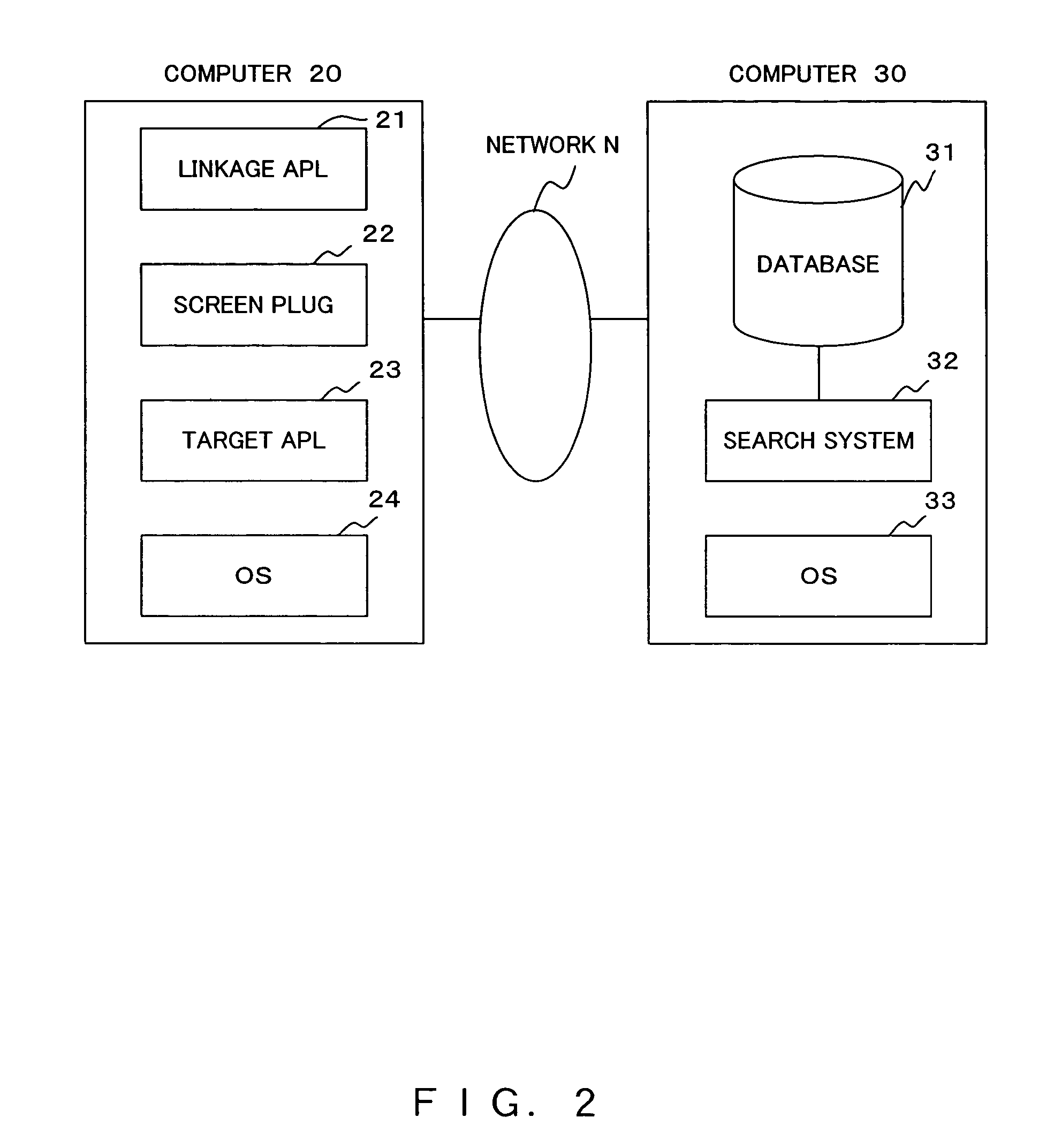
[0064]Next, a configuration of the system relating to the present invention is explained using FIG. 2.

[0065]As described in FIG. 2, a computer 20 has a linkage APL 21, a data linkage support program (hereinafter referred to as a screen plug) 22, a target APL 23 and an operating system (hereinafter referred to as an OS) 24 installed.

[0066]The linkage APL 21 receives data to be linked from the target APL 23 through the screen plug 22, and carries out the processing of the data based on a designated algorithm.

[0067]The screen plug 22 retrieves the screen image data of the display screen from the target APL 23, and acquires data from the screen image data. And it outputs the acquired data to the linkage APL 21. By so doing, the screen plug 22 realizes data linkage between the linkage APL 21 and the target APL 23. The screen plug 22 returns a processing result by the linkage APL 21 to the target APL when required.

[0068]The target APL 23 processes data based on a designated algorithm. The...

second embodiment

[0161]FIG. 31 describes a configuration of a system relating to the As shown in FIG. 31, a target APL 23-1 and a target APL 23-2 are installed in a computer. A screen plug 22-1 captures the data to be linked from the screen of the target APL 23-1, and outputs the data to the target APL 23-2. In response, the screen plug 22-1 receives the result of the linkage process from the target APL 23-2 and outputs it to the target APL 23-1. On the other hand, a screen plug 22-2 captures the data to be linked from the screen of the target APL 23-2, and outputs the data to the target APL 23-1. In response, the screen plug 22-2 receives the result of the linkage process from the target APL 23-1 and outputs it to the target APL 23-2. In other words, the target APL 23-2 is a linkage APL of the target APL 23-1, and the target APL 23-1 is a linkage APL of the target APL 23-2. Consequently, it is possible to link the data in both directions between two programs. In this case, also, neither program is...


PUM


Abstract

A screen plug extracts screen image data of a display screen from a target application and acquired data to be linked from the screen image data. The acquired data is output to a linkage application. Thus the screen plug realizes data linkage between the linkage application and the target application.

Description

CROSS-REFERENCE TO RELATED APPLICATIONS[0001]This application is a continuation of International Application No. PCT / JP2003 / 000802, which was filed on Jan. 28, 2003.BACKGROUND OF THE INVENTION[0002]1. Field of the Invention[0003]The present invention relates to a technique of linking data between applications.[0004]2. Description of the Related Art[0005]It is sometimes the case that system modifications are required so that information, displayed in a display screen of an application (hereinafter referred to as a target APL), can be used by other applications (hereinafter referred to as a linkage APL). In such a case, according to conventional art, the following procedure is followed.[0006]1) A screen displaying data items of the target APL is output on paper etc., and by manual effort, the required data items from the screen are re-entered in the linkage APL.[0007]2) Both APLs are modified so that data linkage between the target APL and the linkage APL can be realized.[0008]Accordi...

Claims


Application Information

Patent Timeline
Patent Type & Authority Patents(United States)
IPC IPC(8): G06F3/048G06F3/00G06F9/44G06F17/30G06K9/20G06K9/46G06K9/64G06K9/74G06T1/00
CPCG06Q30/02G06F17/30256G06F16/5838G06F16/5854
Inventor MAETA, TAKAYUKIKATSUMATA, YUTAKAEGUCHI, SHINICHIKOBARA, KATSUTOSHI
Owner FUJITSU LTD
Learn More