Method and system for false path analysis

a false path and analysis method technology, applied in error detection/correction, program control, instruments, etc., can solve the problems of insufficient optimal component configuration and size, significant time and system resources that may need to be expended, and the generation of false path constraints for a typical design can take several weeks to several months, so as to improve the accuracy of identifying false paths and reduce the amount of manual effort. , the effect of accurate identifying the set of critical problems

Inactive Publication Date: 2011-06-07
CADENCE DESIGN SYST INC
View PDF18 Cites 12 Cited by
  • Summary
  • Abstract
  • Description
  • Claims
  • Application Information

AI Technical Summary

Benefits of technology

[0003]Therefore, it is important to accurately identify the critical paths that really need to be addressed. To date, most approaches have focused on independent efforts to improve the accuracy of RTL static timing estimation or improving the performance of traditional STA at the gate level.
[0004]The typical design flow can involve a large number of static timing analysis (STA) runs in an iterative process. Each time the design is optimized via synthesis, floor planning, place and route, in-place optimization, and / or back annotated post layout, static timing analysis can be performed. For example, STA can generate tens of thousands of critical paths (CPs) with thousands of the CPs being false paths (FPs). Typically, critical paths are analyzed, e.g. manually, and constraints can be created for the false paths, e.g. manually, and fed back to these design tools. Generation of false path constraints for a typical design can take several weeks to several months and is very error prone. For example, very often, incremental changes can be made to a design. Incremental design changes can imply that from one static timing run to the next, many of the same false path constraints still apply. However, design changes may cause some of the constraints to become invalid. The false path constraints that are manually generated initially might not be re-verified when incremental changes are made to the design. The false path constraints that are no longer valid (invalid constraints) can cause a bad design to be implemented. Using the proposed method, existing constraints can be automatically verified and / or automatically regenerated, ensuring accurate and efficient design implementation.
[0006]Embodiments of the present invention provide a method and system for performing false path analysis to accurately identify the set of critical paths which must be addressed in a circuit design. In one embodiment, a set of false paths is identified based upon analysis of both implementation-specific design data and non-implementation-specific design data. Embodiments of the invention provide automatic methods and systems for gate-level static timing false path analysis, identification, constraint generation and / or verification using architectural information. Accurate gate level timing data in conjunction with the architectural design data and formal methods can be used to identify false paths. The combination of formal techniques with static timing analysis to identify false paths using information from the architectural information yields improved results in identifying false paths. Some embodiments can use non-formal techniques such as simulation.
[0008]In one or more embodiments of the invention, static timing paths at the gate-level can be linked to the architectural information via techniques such as logic cone and / or state point correspondence, such as commonly used in equivalence checking (EC). The gate-level static timing paths can be analyzed in the context of the architectural information to identify false paths. The analysis of gate-level paths in the context of the architectural information can enable identification of false paths that cannot be identified in the context of gate-level information alone. Furthermore this automated approach can be less error prone and / or much more efficient than existing techniques which are commonly manual techniques.

Problems solved by technology

It is generally not preferred to make such design modifications if they can be avoided, since each such modification consumes time and system resources, as well as possibly introducing less optimal component configurations and sizes.
Since the number of such critical paths may exceed, for example, tens of thousands for large gate-level designs in a modern design, a significant amount of time and system resources may need to be expended to address all of the identified critical paths.
Generation of false path constraints for a typical design can take several weeks to several months and is very error prone.
However, design changes may cause some of the constraints to become invalid.
The false path constraints that are manually generated initially might not be re-verified when incremental changes are made to the design.
The false path constraints that are no longer valid (invalid constraints) can cause a bad design to be implemented.
For example, some static timing tools detect paths that are logically never used with ATPG techniques; however, these techniques have been limited to the gate level without consideration of additional constraints that can be imposed by architectural information.
Moreover, many false paths cannot be identified at the gate level.
The problems of identifying which critical paths are real and which as false can often involve human intervention.
There are tools that explore static timing estimation at the RTL level; however, the tools that operate at the RTL level do not consider the actual critical paths in the gate level design.
These tools are for timing estimation only and are not accurate enough for timing sign off.
The manual analysis of these critical paths can be quite time consuming and error prone, adding weeks to months in the design process.
Errors in the static timing analysis could lead to the manufacture of a bad design.

Method used


Image

  • Method and system for false path analysis
  • Method and system for false path analysis
  • Method and system for false path analysis

Examples


Embodiment Construction

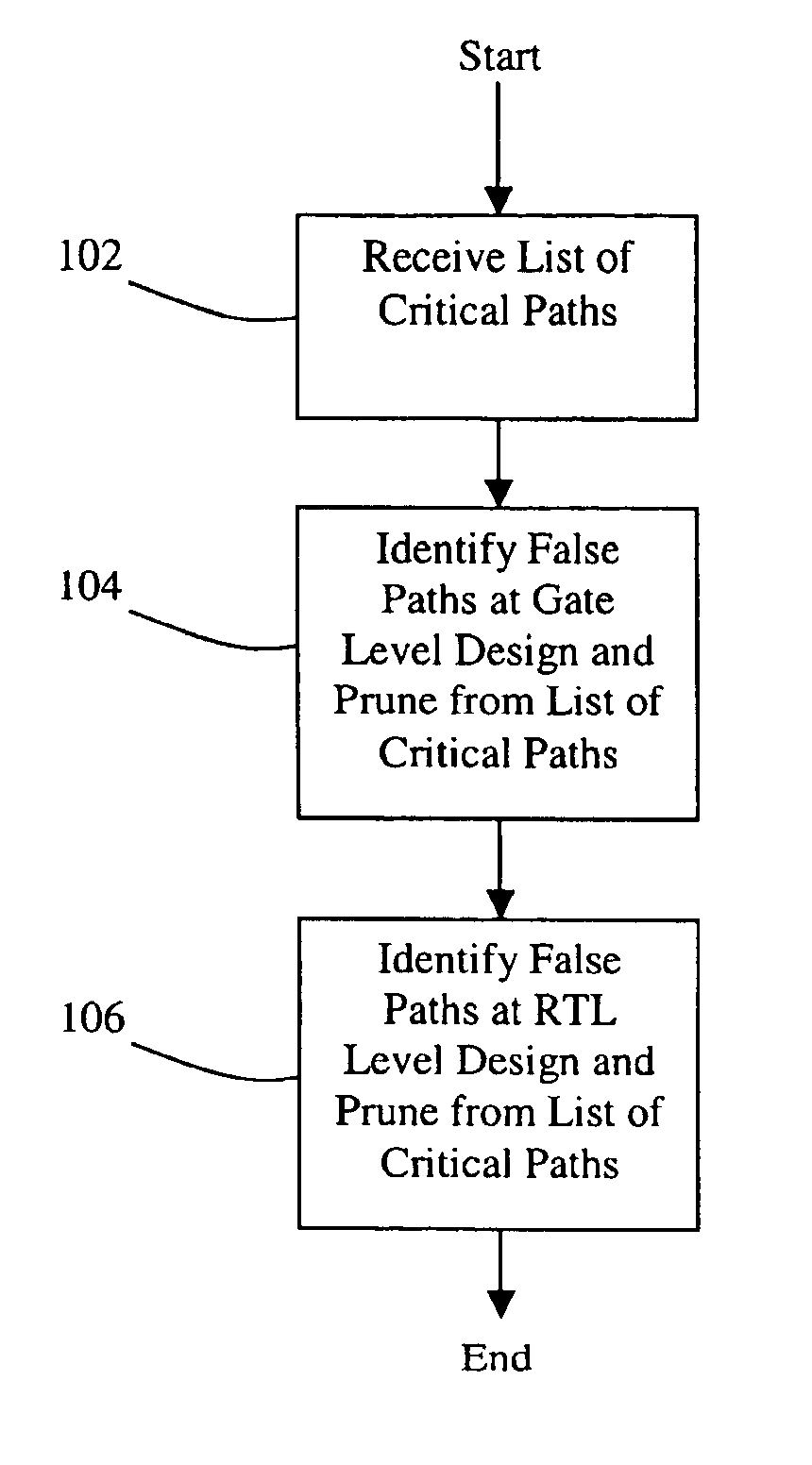
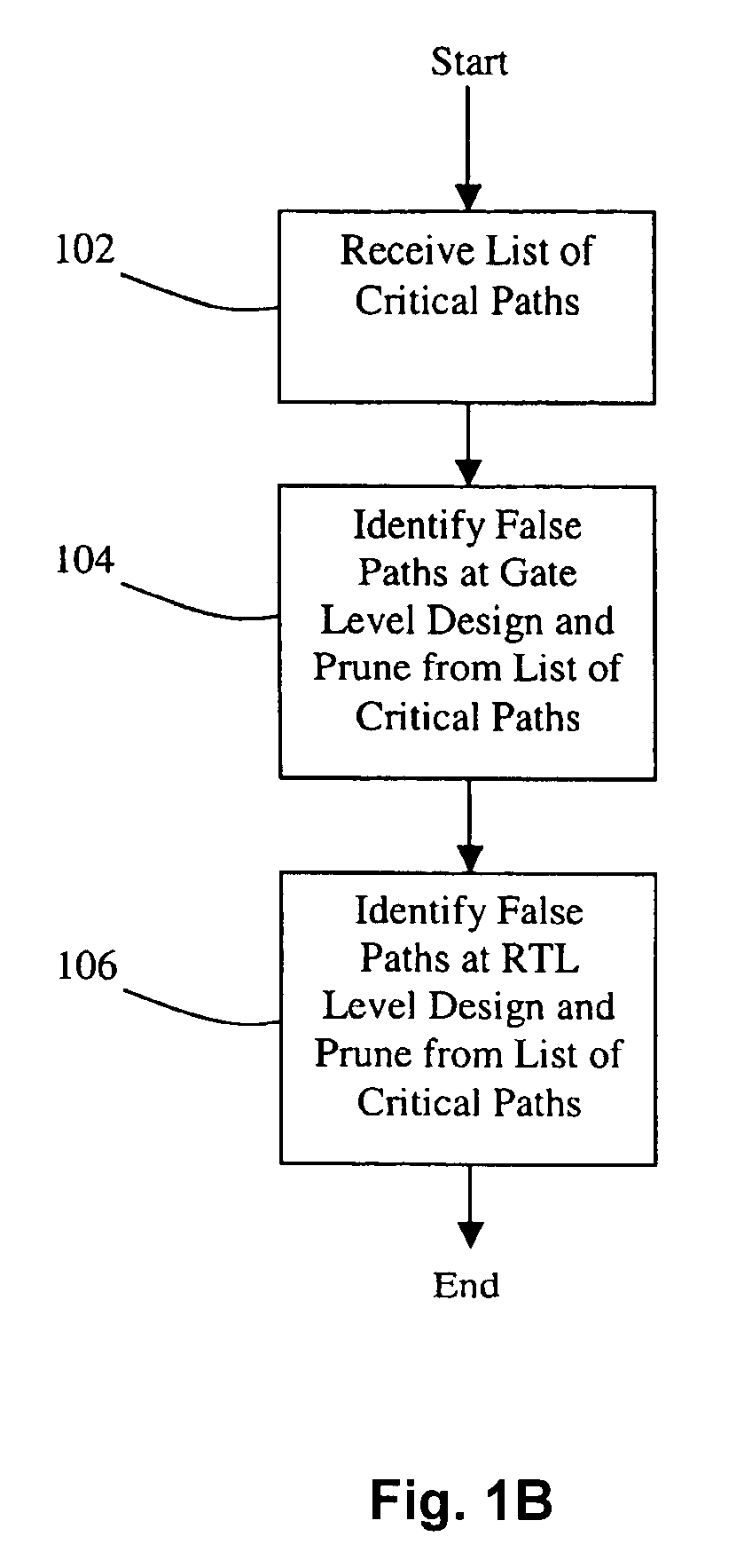
[0019]The present invention provides a method and system for performing false path analysis to accurately identify the set of critical paths that must be addressed in a circuit design. One advantage of identifying false paths (FPs) is that this identification can be used to reduce the number of critical paths that must be analyzed, redesigned, and / or modified to meet the given timing requirements for a circuit design.

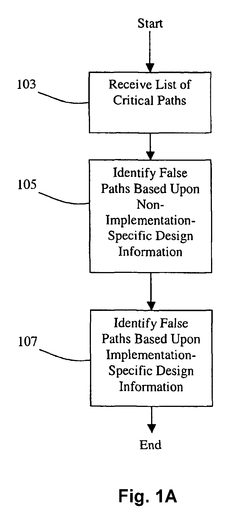
[0020]FIG. 1A shows a high-level flowchart of a process for performing false path analysis according to an embodiment of the invention. At 103, the process receives an initial list of one or more critical paths for the circuit design. The list of critical paths can be generated, for example, using a static timing analysis tool. By analyzing each critical path, it can be determined if the path is real or false (false paths) in the context of the design's architectural design data (also referred to as architectural information).

[0021]At 105, the process identifies a set o...


PUM


Abstract

Disclosed are methods and systems for performing false path analysis. In one approach, the methods and systems identify a set of zero or more false paths based upon both implementation-specific design data and non-implementation-specific design data. In some approaches, disclosed are methods and systems for performing automated gate-level static timing false path analysis, identification, constraint generation, and / or verification using architectural information. Static timing paths at the gate-level can be linked to the architectural information via mapping techniques found in equivalence checking (EC). The gate level static timing paths can be analyzed in the context of the architectural information to identify false paths.

Description

CROSS-REFERENCE TO RELATED APPLICATIONS[0001]The present application is a divisional of U.S. application Ser. No. 10 / 836,700, filed on Apr. 29, 2004, which claims the benefit of U.S. Provisional Application No. 60 / 466,698, filed on Apr. 29, 2003, both of which are hereby incorporated by reference in their entireties.BACKGROUND AND SUMMARY[0002]Static timing analysis (STA) can determine if there exist paths in an electrical circuit design with delays that exceed a given timing threshold. Such paths are commonly known as critical paths (CPs). When such a critical path is identified, the portion of the design associated with the critical path may need to be modified to satisfy the required timing thresholds. It is generally not preferred to make such design modifications if they can be avoided, since each such modification consumes time and system resources, as well as possibly introducing less optimal component configurations and sizes. Since the number of such critical paths may exce...

Claims


Application Information

Patent Timeline
Patent Type & Authority Patents(United States)
IPC IPC(8): G06F17/50
CPCG06F17/5031G06F30/3312
Inventor SIARKOWSKI, BRET
Owner CADENCE DESIGN SYST INC
Why Eureka
Try Eureka