
Threading device on a numerically controlled lathe

a numerical control and threading technology, applied in the direction of thread cutting machines, automatic/semiautomatic turning machines, turning apparatus, etc., can solve the problems of affecting the surface negatively affecting the precision and quality of the resulting thread, and the use of a resilient element in the form of a belt, so as to achieve the effect of improving the cutting threading method and reducing the roughness

Active Publication Date: 2011-06-14
GILDEMEISTER ITALANA
View PDF8 Cites 0 Cited by
  • Summary
  • Abstract
  • Description
  • Claims
  • Application Information

AI Technical Summary

Benefits of technology

The solution enables the production of high-precision, variable pitch threads with reduced surface roughness and machining defects, resulting in a compact, flexible, and efficient threading device that minimizes maintenance and improves thread quality.

Problems solved by technology

The prior method for making the above mentioned threads, however, is not a continuous cutting method, but an interrupted cutting operation, like a milling machining operation, and this type of machining greatly stresses the driving means; moreover, because of unavoidable clearances, the surfaces of the resulting threads are inevitably affected by machining defects and rags.
Usually, in prior devices, the threading tools are driven by a driving motor through a series of gears which, because of their nature, necessarily require a minimum clearance, to provide a proper mutual meshing, and this clearance, even if it has a minimum value, negatively affects the precision and quality of the resulting thread surface.
This approach, however, has the drawback that a resilient element in the form of a belt must be used in order to transmit the rotary motion from the driving motor to the machining tool.
The use of a belt generates inevitable undesired oscillations in the rotary movement of the tool that must be subjected to continuous control.
Moreover, the driving belt must be subjected to periodic controls for its inevitable wear and to repeatedly accomplish the tensioning thereof.
Thus, both the above mentioned gear assembly and driving belt, as conventionally used for rotatively driving prior threading tools, cause an undesired increase of the overall size of the device.

Method used


Image

  • Threading device on a numerically controlled lathe
  • Threading device on a numerically controlled lathe
  • Threading device on a numerically controlled lathe

Examples


Embodiment Construction

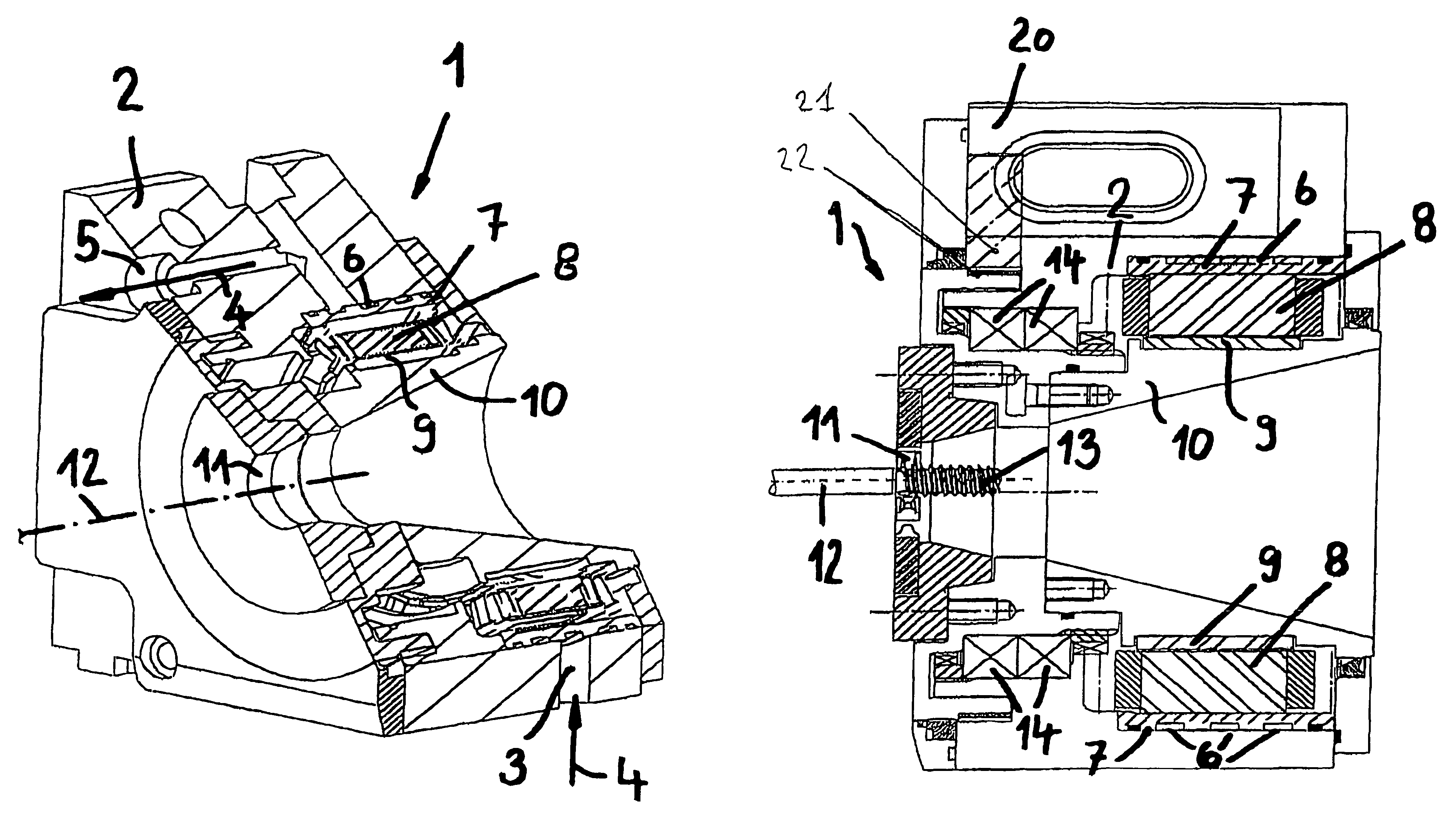
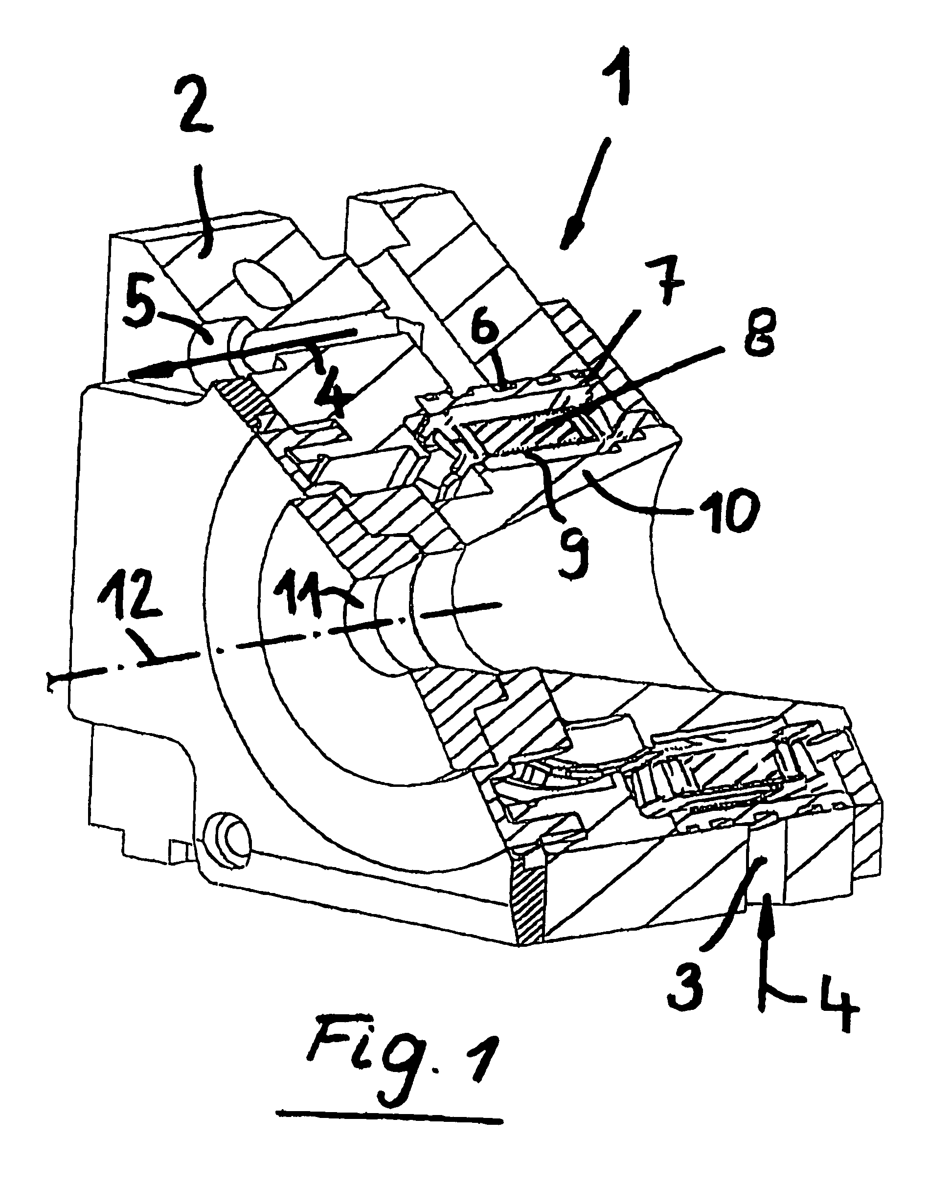
[0027]As shown in FIG. 1, the threading device according to the present invention, which has been generally indicated by the reference number 1, comprises a supporting assembly or body 2, having a throughgoing opening 3 for supplying a refrigerating and lubricating fluid 4.

[0028]The supporting body or assembly 2 is mounted on a slide of a machine tool, not herein shown.

[0029]The refrigerating and lubricating fluid passes through channels, not specifically shown, of the supporting assembly 2, as it will be disclosed in a more detailed manner hereinafter, said fluid 4 exiting the supporting assembly 2 through an outlet channel 5.

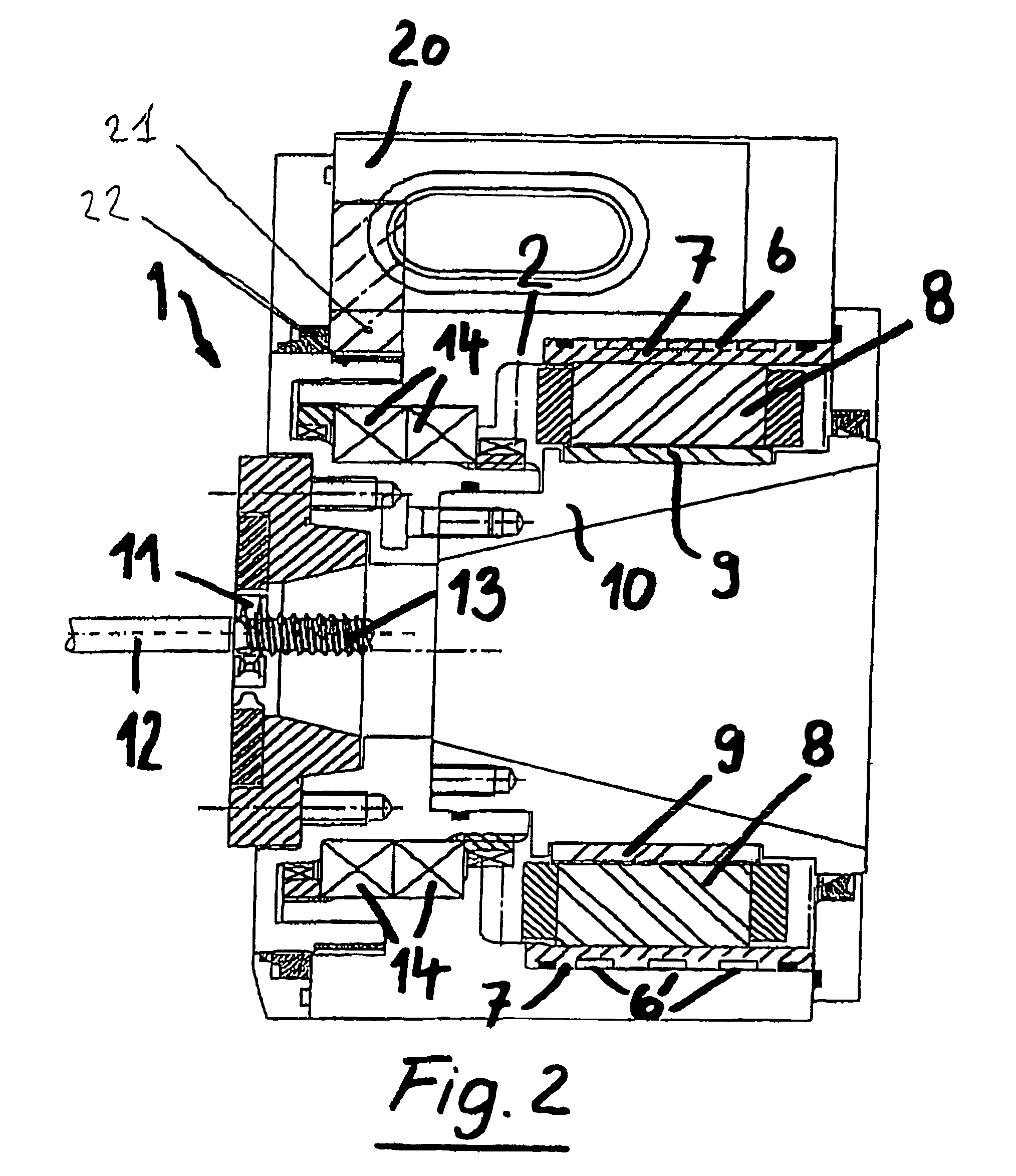
[0030]Before exiting said supporting assembly or body 2, the refrigerating fluid 4 passes through a plurality of circumferential channels 6 of an annular body 7 encompassing the stator 8 operating in cooperation with a rotor 9 integral with a further body 10 which, at a region 11 thereof, supports a plurality of machining tools (not shown in FIG. 1) for machin...


PUM

PropertyMeasurementUnit
rotary speedaaaaaaaaaa
structureaaaaaaaaaa
surface qualityaaaaaaaaaa

Abstract

A piece-threading device on a numerically controlled lathe comprises a supporting assembly having an inner rotatively driven body which, on a side thereof facing a workpiece to be threaded, comprises a plurality of threading tools, the rotatively driven body having a built-in electrical rotor (9) to which an electric stator (8) also built-in in the supporting assembly is operatively coupled, the stator (8) having a plurality of circumferential channels (6) for circulating therethrough a refrigerating and lubricating fluid.

Description

BACKGROUND OF THE INVENTION[0001]The present invention relates to a piece-threading device to be used on a numerically controlled lathe.[0002]As is known, in the medical field are conventionally used screws, stems or other mechanical pieces to be screwed into the bone structure of a patient.[0003]At present, the best method used in the prior art for making threaded elements to be used in the medical or dental field, is a specifically designed cutting process, the so-called “swivel” threading process or, in a word-wide manner, the “Thread Whirling Process”.[0004]Prior methods allow to make threaded pieces with a variable pitch thread, a very long pitch thread, highly buttressed threads, bevel threads or variably buttressed threads.[0005]It should be apparent that the selection of the thread will depend on the specific bone structure, the screw must be screwed into.[0006]The prior machining method allowing to make different types of threads on a lathe, also allows to machine, without ...

Claims


Application Information

Patent Timeline
Patent Type & Authority Patents(United States)
IPC IPC(8): B23B25/00B23B5/46
CPCA61B17/866B23G1/34B23G2240/12Y10T82/2502Y10T82/30Y10T82/25B23G2240/60B23G2240/40
Inventor RIGOLONE, FRANCOROTA, RENATOGERVASONI, OSCAR
Owner GILDEMEISTER ITALANA
Features
  • Generate Ideas
  • Intellectual Property
  • Life Sciences
  • Materials
  • Tech Scout
  • Unparalleled Data Quality
  • Higher Quality Content
  • 60% Fewer Hallucinations
Learn More