Bathtub whirlpool toy
a whirlpool and bathtub technology, applied in the field of toys, can solve the problems of increasing the flow rate and the size of the whirlpool formed, reducing the resistance,
- Summary
- Abstract
- Description
- Claims
- Application Information
AI Technical Summary
Benefits of technology
Problems solved by technology
Method used
Image
Examples
first embodiment
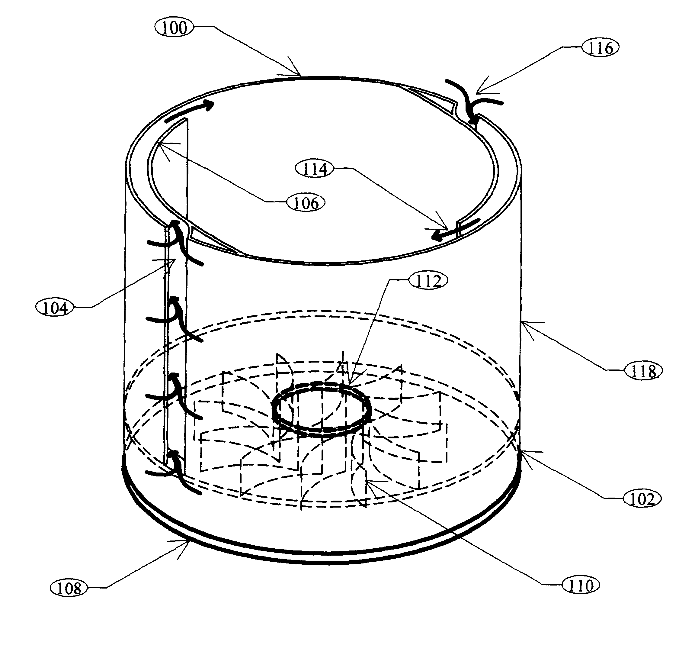
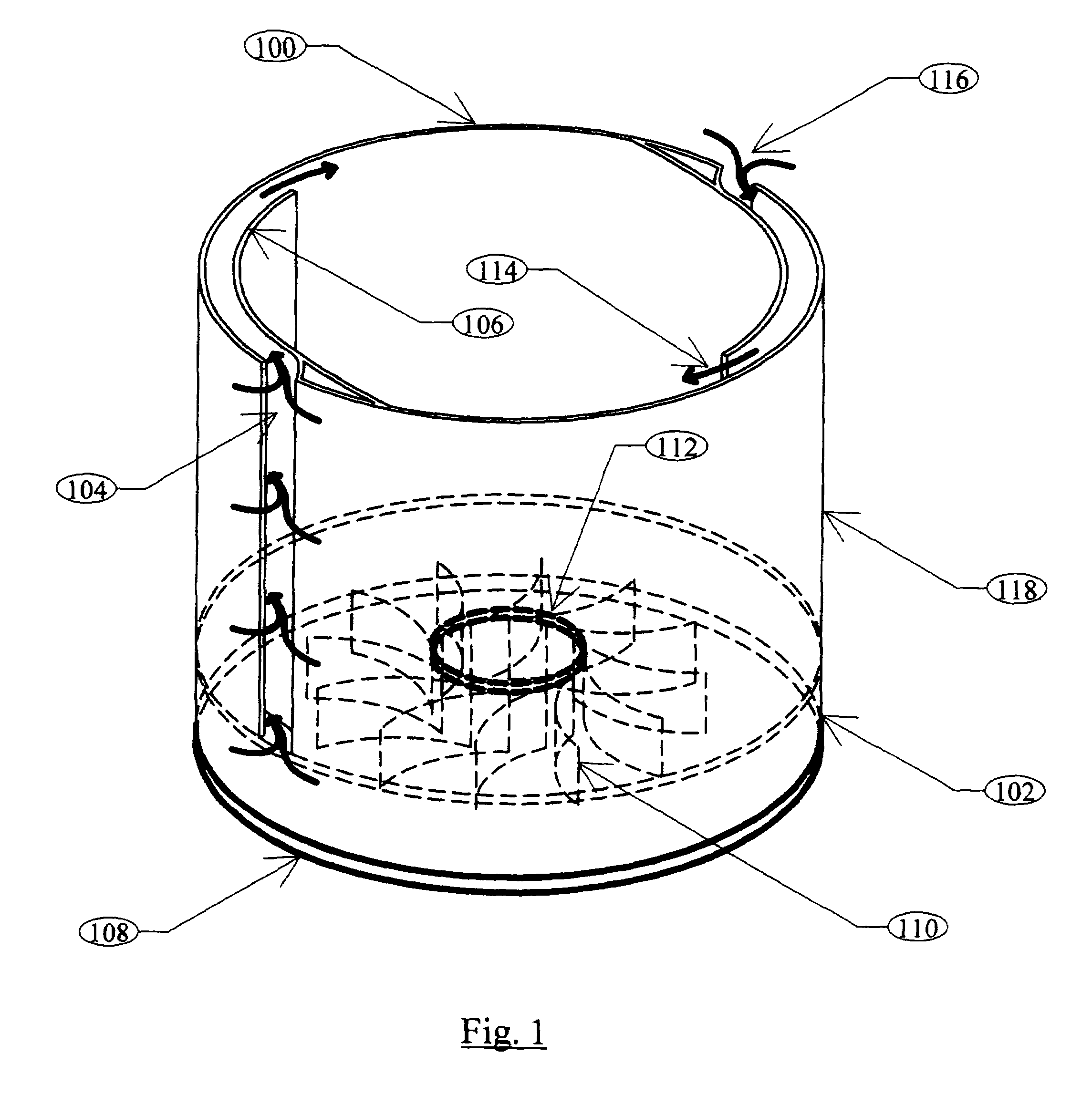
[0120]FIG. 1 is a partially transparent perspective view of the device 100. Lower recuperation chamber 102 and upper recuperation chamber (defined by wall 118) are separated by a floor into two different chambers, connected only by interior space outlet aperture 112. A vortex may be easily formed in the upper chamber, while the lower chamber (defined by the bottom of the bathtub and the bottom of the interior vortex chamber) aids in speeding flow and preventing water from developing undesirable back pressure by means of recuperation fin / vane 110, which recovers kinetic energy from the vortex.
[0121]Inlet slot 104 is defined by inner slot wall 106 and accepts inlet flow 116, water which comes in from a large sink or bathtub partially full of water. Inner slot wall 106 channels and directs the flow to produce a desirable vortex flow 114.
[0122]Lip / gasket 108 helps seal the recuperation chamber from the ambient water in the household fixture so as to aid in preventing water from bypassin...
fourth embodiment
[0134]FIG. 4 is a cross sectional diagram of the device, showing details of the recuperation chamber. Side wall 402 defines interior space 404 having top 406. In the presently preferred embodiment and best mode now contemplated, top 406 is an opening allowing users to experiment and play with the vortex, for example by feeling it, placing water toys into it, or using an adapter (explained in reference to FIG. 6) in a dynamic / interactive mode. In alternative embodiments, however, top 406 may be transparent, a smaller aperture, screened and so on.
[0135]Inlet slot 408 is defined by inlet slot edges 410, 412, while interior outlet aperture 414 may be clearly seen in the center of the interior bottom 416. The interior outlet aperture 414 may be placed at locations other than the center of the interior bottom 416 (that is, locations away from the center of the interior space 404) in alternative embodiments.
[0136]Recuperation chamber 418 (again defined by household fixture bottom 422) may ...
fifth embodiment
[0139]FIG. 5 is partially transparent bottom view of the device showing details of a fifth embodiment and the recuperation chamber. Recuperation chamber 502 is defined by side wall of recuperation chamber 504 and has interior outlet aperture 506 (which of course functions as an inlet for the recuperation chamber 502) and further has recuperation outlet aperture 508. Vanes / fins 510 may be straight and still function to recover kinetic energy from the water, or may be shallow curves, angled, bent and other shapes. Fins as used herein includes patterns of posts or pins, bumps, ridges, irregularities, and so on. The vanes / fins may extend entirely across the chamber from top to bottom, or may extend partially from either the top or bottom of the chamber, or may extend from the sides or center of the chamber, may be irregular, and may vary in number.
[0140]FIG. 6 is a planform view of an adapter according to the device, allowing interactive and dynamic user control of the vortex.
[0141]Adap...
PUM
 Abstract
Description
Claims
Application Information
 - R&D
- Intellectual Property
- Life Sciences
- Materials
- Tech Scout
- Unparalleled Data Quality
- Higher Quality Content
- 60% Fewer Hallucinations
Browse by: Latest US Patents, China's latest patents, Technical Efficacy Thesaurus, Application Domain, Technology Topic, Popular Technical Reports.
© 2025 PatSnap. All rights reserved.Legal|Privacy policy|Modern Slavery Act Transparency Statement|Sitemap|About US| Contact US: help@patsnap.com


