Device and method for manufacturing a particulate filter with regularly spaced micropores

a technology of micropores and filters, which is applied in the direction of optical radiation measurement, printers, nuclear engineering, etc., can solve the problems of high or higher specific flow resistance per unit area of filters constructed as disclosed, and the area around them is very sensitive to various chemical agents

Inactive Publication Date: 2011-06-14
UNIV HOUSTON SYST
View PDF14 Cites 31 Cited by
  • Summary
  • Abstract
  • Description
  • Claims
  • Application Information

AI Technical Summary

Problems solved by technology

These defects make the areas around them very sensitive to various chemical agents.
Often, however, filters constructed as disclosed have suffered from a high or higher specific flow resistance per unit area compared to other filter technologies.

Method used


Image

  • Device and method for manufacturing a particulate filter with regularly spaced micropores
  • Device and method for manufacturing a particulate filter with regularly spaced micropores
  • Device and method for manufacturing a particulate filter with regularly spaced micropores

Examples


examples

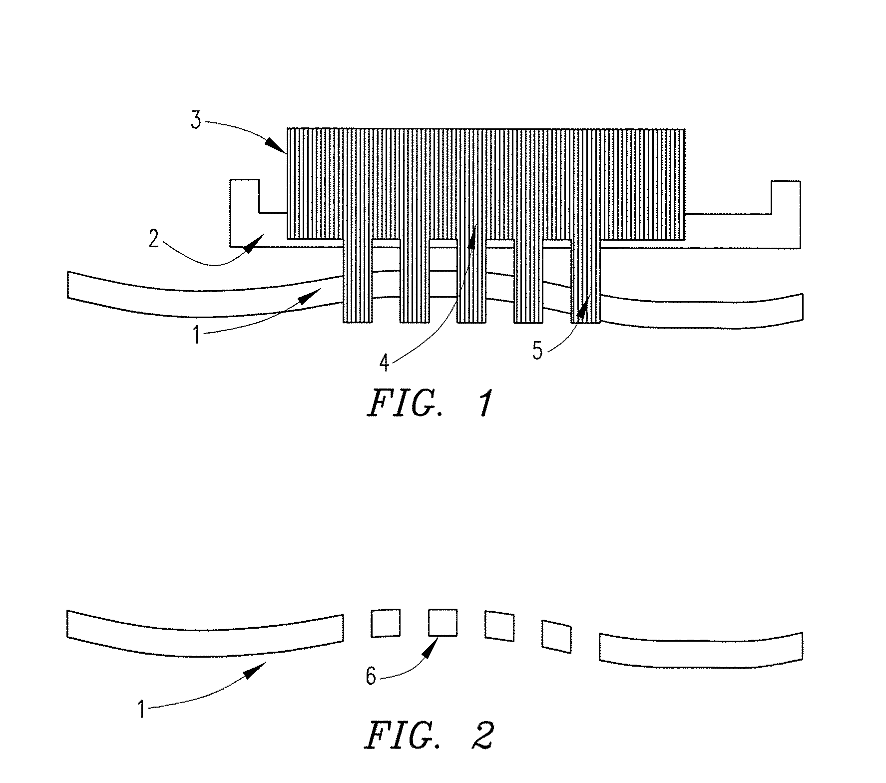
[0068]FIG. 1 is an illustration of beam (3) of energetic particles impinges on a substantially planar mask (2) perforated by stencil openings (4). A structured beam of transmitted beamlets (5) damages the non-planar membrane substrate (1) in a highly uniform array of regularly spaced regions.

[0069]FIG. 1 illustrates the exposure process in which a substantially parallel beam (3) of energetic particles (ions, electrons, or neutral energetic atoms or molecules) impinges on a substantially planar mask (2) perforated by stencil openings (4). Transmitted beamlets (5) form a structured beam that damages the non-planar membrane substrate (1) in a highly uniform array of regularly spaced regions. FIG. 2 shows that after development in a suitable solvent, the non-planar membrane substrate (1) becomes permeated by a highly uniform array of regularly spaced pores (6). The substrate may deform from its original shape during development.

[0070]FIG. 2 is an illustration of a membrane substrate aft...


PUM

PropertyMeasurementUnit
energyaaaaaaaaaa
thicknessaaaaaaaaaa
thicknessaaaaaaaaaa

Abstract

Various embodiments disclose devices and methods for fabricating microporous particulate filters with regularly space pores wherein sheet membrane substrates are exposed to energetic particle radiation through a mask and the damaged regions removed in a suitable developer. The required depth of field is achieved by using energetic particles to minimize diffraction and an energetic particle source with suitably small diameter.

Description

CROSS REFERENCE TO RELATED APPLICATIONS[0001]This application claims priority to U.S. Provisional Application No. 60 / 894,593, filed on March 13, 2007. The entirety of US Provisional Application No. 60 / 894,593 is incorporated herein by reference.GOVERNMENT SPONSORSHIP[0002]This invention was made with government support under grant no. ECS-0404308 awarded by the National Science Foundation. The government has certain rights in the invention.BACKGROUND OF THE INVENTION[0003]1. Field of the Invention[0004]The present invention relates to a method for manufacturing a particulate filter comprising a membrane with a high density array of regularly spaced micropores and a macroporous support.[0005]2. Description of the Background Art[0006]A lithographic apparatus or device is a machine that applies a desired pattern onto a substrate, usually onto a target portion of the substrate, such as a membrane substrate. A lithographic device can be used, for example, in the manufacture of integrated...

Claims


Application Information

Patent Timeline
Patent Type & Authority Patents(United States)
IPC IPC(8): G21K5/02G21K5/08
CPCB01D67/0034B01D71/48G03B27/42G03F7/0015B01D2323/42Y10T428/249921B01D2325/028B01D71/481
Inventor WOLFE, JOHN C.RUCHHOEFT, PAUL
Owner UNIV HOUSTON SYST
Why Eureka
Try Eureka