Liquid crystal display device and method for driving the same

a technology of liquid crystal display and display device, which is applied in the direction of static indicating device, optics, instruments, etc., can solve the problems of increasing manufacturing cost and unsatisfactory display performance, and achieve the effect of reducing the applied voltage and minimizing the unevenness of display

Inactive Publication Date: 2011-06-14
SHARP KK
View PDF15 Cites 1 Cited by
  • Summary
  • Abstract
  • Description
  • Claims
  • Application Information

AI Technical Summary

Benefits of technology

[0015]In order to overcome the problems described above, preferred embodiments of the present invention provide a liquid crystal display device that can present an image of quality with the unevenness of display minimized and also provide a liquid crystal display device that can be driven with a reduced applied voltage.
[0040]According to any of various preferred embodiments of the present invention described above, an oscillation voltage is applied, as a superposed voltage on a gray-scale voltage, to each liquid crystal capacitor. Thus, the ratio of the variation in luminance to the variation in gray-scale voltage (i.e., the gradient of a V-Y curve) can be reduced. As a result, the unevenness of display can be minimized and an image of quality can be displayed. The ratio of the variation in luminance to the variation in gray-scale voltage can be reduced particularly effectively in a range where the gray-scale voltage is relatively low. For that reason, the display quality of an NB mode liquid crystal display device, among other things, can be improved significantly. In addition, by superposing the oscillation voltage, the threshold voltage of the electro-optic characteristic can be reduced, thus providing a liquid crystal display device that can be driven with a lower applied voltage.

Problems solved by technology

However, the display performance (e.g., the viewing angle characteristic, in particular) thereof is not fully satisfactory.
Accordingly, in the IPS or MVA mode liquid crystal display device, the patterning accuracy of TFTs and other circuit components and the performance of driver circuits (including various signal voltage generators) must be increased, thus raising the manufacturing cost significantly.
Nevertheless, this problem is commonly observed in every liquid crystal display device, although their degrees are different.

Method used


Image

  • Liquid crystal display device and method for driving the same
  • Liquid crystal display device and method for driving the same
  • Liquid crystal display device and method for driving the same

Examples


Embodiment Construction

[0062]Hereinafter, a liquid crystal display device and its driving method according to preferred embodiments of the present invention will be described with reference to the accompanying drawings.

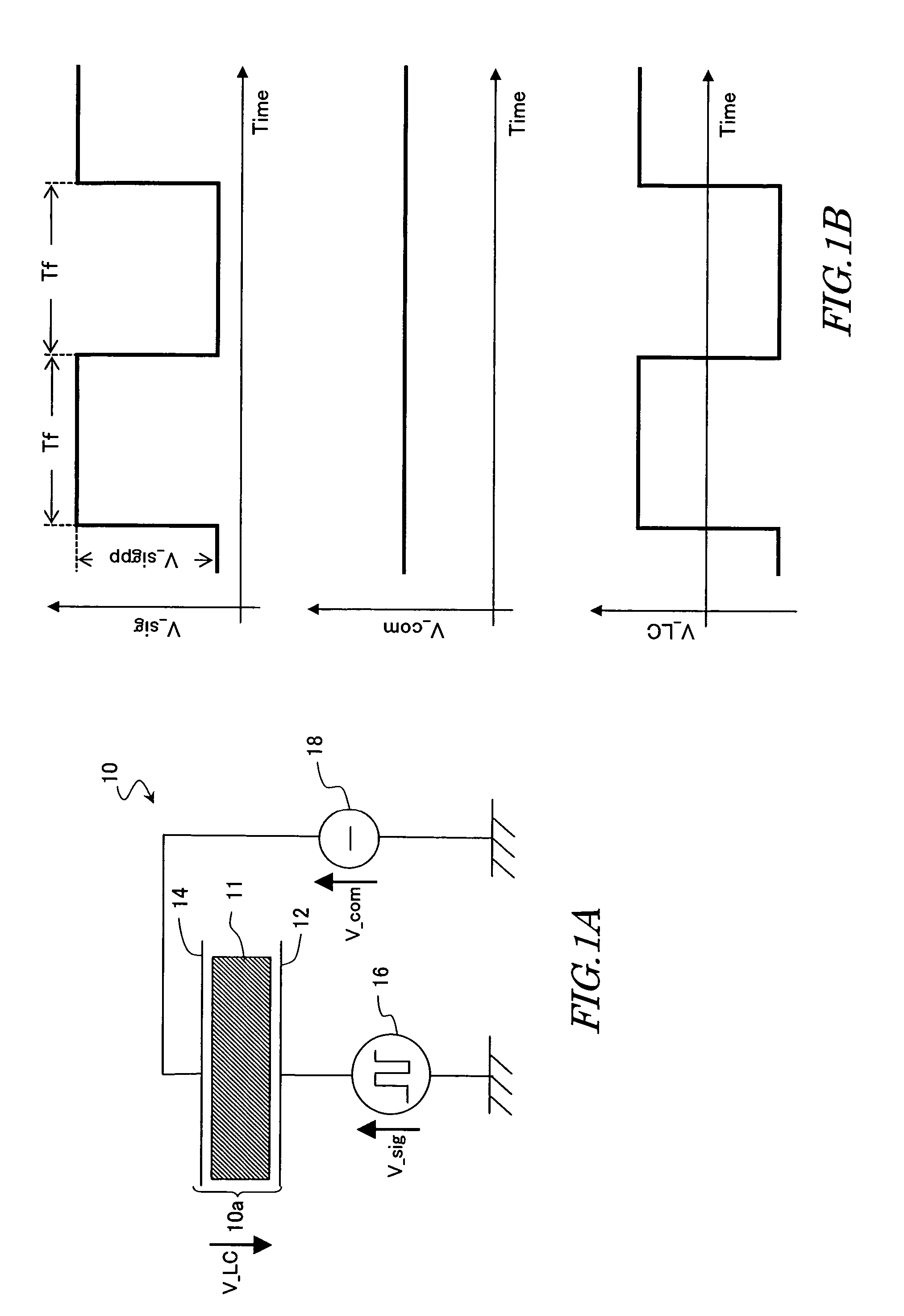
[0063]First, a conventional typical LCD driving method will be described with reference to FIGS. 1A and 1B.

[0064]FIG. 1A schematically illustrates the configuration of one pixel in a conventional typical LCD 10. This pixel includes a liquid crystal capacitor 10a consisting of a liquid crystal layer 11 and two electrodes (namely, a pixel electrode 12 and a counter electrode 14) for applying a potential to the liquid crystal layer 11. A predetermined gray-scale voltage V_sig is applied from a gray-scale voltage generator 16 to the pixel electrode 12, while a counter voltage is applied from a counter voltage generator 18 to the counter electrode 14.

[0065]In an active-matrix-addressed LCD, each pixel usually has a storage capacitor to hold the voltage at the liquid crystal capacitor 10a and an ...


PUM

PropertyMeasurementUnit
oscillation voltageaaaaaaaaaa
voltageaaaaaaaaaa
threshold voltageaaaaaaaaaa

Abstract

A liquid crystal display device includes a plurality of pixels, each of which includes a liquid crystal capacitor made up of a liquid crystal layer and two electrodes to apply a voltage to the liquid crystal layer. While the device is conducting a display operation, an oscillation voltage, which oscillates a number of times within a single vertical scanning period, and a predetermined gray-scale voltage are applied to the liquid crystal capacitor of an arbitrary one of the pixels.

Description

[0001]This Nonprovisional application claims priority under 35 U.S.C. § 119(a) on Patent Application Nos. JP 2003-300177 filed Aug. 25, 2003 and JP 2004-232455 filed on Aug. 9, 2004, the entire contents of each of which are hereby incorporated herein by reference.BACKGROUND OF THE INVENTION[0002]1. Field of the Invention[0003]The present invention relates to a liquid crystal display device and a method for driving the device.[0004]2. Description of the Related Art[0005]A liquid crystal display (LCD) is a flat-panel display that has a number of advantageous features including high resolution, drastically reduced thickness and weight, and low power dissipation. The LCD market has been rapidly expanding recently as a result of tremendous improvements in its display performance, significant increases in its productivity, and a noticeable rise in its cost effectiveness over competing technologies.[0006]A twisted-nematic (TN) mode liquid crystal display device, which used to be used exten...

Claims


Application Information

Patent Timeline
Patent Type & Authority Patents(United States)
IPC IPC(8): G09G3/36G02F1/136G02F1/133G09G3/20H01L29/786
CPCG09G3/3611G09G3/3655G09G2300/0876G09G2340/16G09G2320/0233G09G2320/0252G09G2310/06G02F1/133
Inventor SHIMOSHIKIRYOH, FUMIKAZU
Owner SHARP KK
Why Eureka
Try Eureka