
Chemical reactor for nitrogen oxide removal and method of removing nitrogen oxide

a chemical reactor and nitrogen oxide technology, applied in the direction of chemistry apparatus and processes, dispersed particle separation, separation processes, etc., can solve the problems of high fuel consumption, sharp drop-off of catalyst activity, and inability to control nitrogen oxide emission, so as to reduce current

Inactive Publication Date: 2005-08-04
NAT INST OF ADVANCED IND SCI & TECH
View PDF1 Cites 12 Cited by
  • Summary
  • Abstract
  • Description
  • Claims
  • Application Information

AI Technical Summary

Benefits of technology

[0012] In view of this, and in an effort to solve the above problems, the inventors conducted research aimed at developing technology for reducing the amount of oxygen that is ionized at the cathode of an electrochemical cell, even when an excess of oxygen is present in a combustion exhaust gas, and thereby developing technology for decreasing the resistance of an electrochemical cell and at the same time reducing the amount of current needed to decompose nitrogen oxides, and reducing the applied voltage. Specifically, it is an object of the first aspect of the present invention to provide a chemical reactor with which the amount of current required to decompose nitrogen oxides is reduced by decreasing the amount of oxygen that is ionized and flows through an electrochemical cell, even when there is an excess of oxygen present in a combustion exhaust gas, and the resistance of the electrochemical cell is also lowered, which allows the applied voltage to be reduced and nitrogen oxide emission control to be performed at higher efficiency and lower power consumption.
[0013] Also, the present invention was conceived in order to solve the above problems, and the inventors arrived at the present invention upon discovering that the stated object can be achieved, and a treatment substance can be treated at higher efficiency and lower power consumption, by disposing an electrode layer composed of a mixture of an ion conductor and an electron conductor at the lower portion where the chemical reaction occurs, and optimizing the mix ratio of the ion conductor and the electron conductor so that the supply of electrons with respect to the oxygen that serves as the active site of the chemical reaction, and the process of moving and removing the ionized oxygen can be carried out more efficiently.
[0014] Specifically, it is an object of the second aspect of the present invention to provide a novel chemical reactor that fundamentally solves the problems with the above prior art, which makes possible 1) the optimization of the structures of the path for supplying electrons that ionize oxygen and of the path for eliminating ionized oxygen from the catalyst reaction surface, and 2) the resulting decrease in the electrical power needed to decompose nitrogen oxides with an electrochemical cell process, and perform nitrogen oxide emission control at higher efficiency and lower power consumption.

Problems solved by technology

However, since there is an excess of oxygen in the combustion exhaust gas emitted from diesel engines and lean engines that afford better fuel economy, the adsorption of oxygen at the surface of the three-way catalytic converter results in a sharp drop-off in catalyst activity, to the point that nitrogen oxide emission control becomes impossible.
Consequently, one method for removing the oxygen from a catalyst surface has been to intermittently introduce hydrocarbons in order to react with the oxygen and release it to outside the system, but this inevitably leads to higher fuel consumption.
With the above conventional methods, however, if an excess of oxygen is present in the combustion exhaust gas, the oxygen will be preferentially ionized at the electrodes and flow through the solid electrolyte, so a larger amount of current is required in order to decompose the nitrogen oxides, which means that a higher voltage has to be applied and power consumption is higher, and this poses a major obstacle to practical use.
Also, with an electrochemical cell that makes use of a solid electrolyte membrane, nitrogen oxides can indeed be decomposed or removed merely by applying voltage, but a problem is that the temperature has to be high (400° C. or higher) in order to increase the ion conductivity of the solid electrolyte.
Also, particularly when the exhaust gas is cold immediately after the combustor has been started up, the above-mentioned electrochemical cell does not exhibit adequate performance, and nitrogen oxides cannot be removed for a time, and this problem is particularly pronounced with diesel engines, lean engines, and so forth that are frequently started and stopped.
A problem with this method, however, was that a reducing agent such as a hydrocarbon was needed to reduce excess oxygen, which hampered efforts at energy conservation.

Method used


Image

  • Chemical reactor for nitrogen oxide removal and method of removing nitrogen oxide
  • Chemical reactor for nitrogen oxide removal and method of removing nitrogen oxide
  • Chemical reactor for nitrogen oxide removal and method of removing nitrogen oxide

Examples


example 1

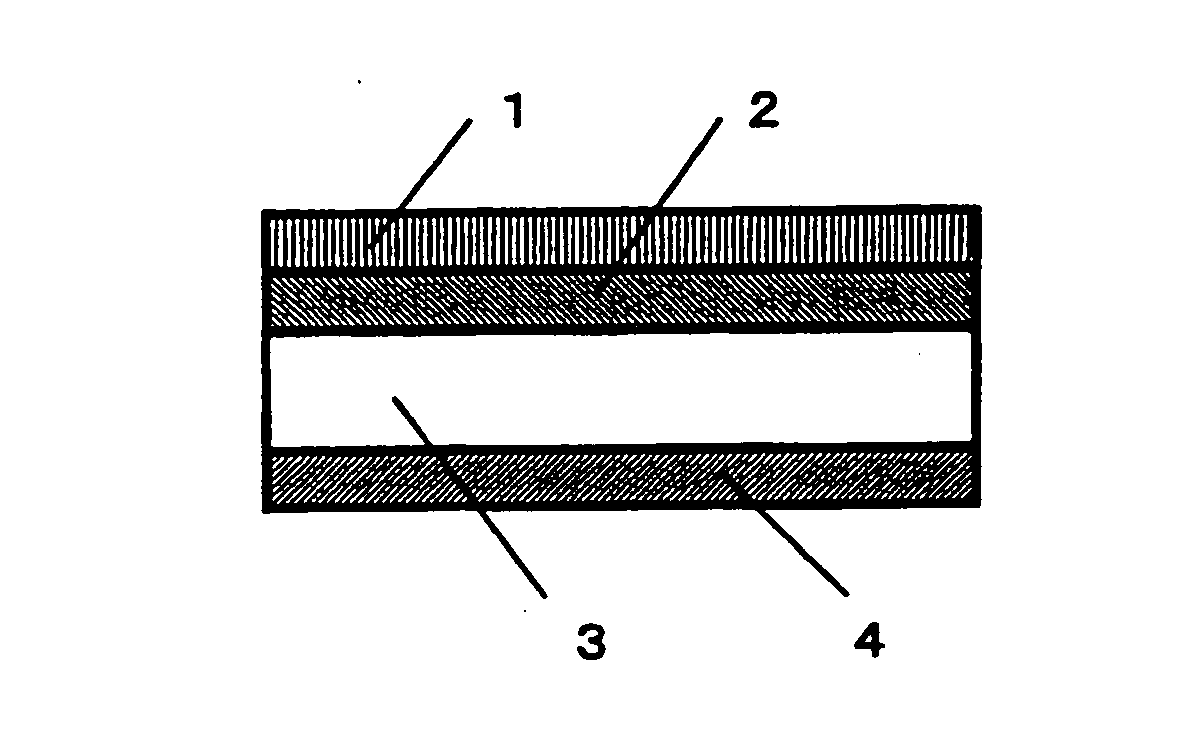
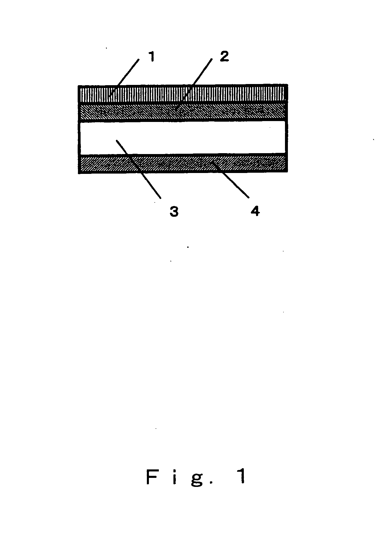
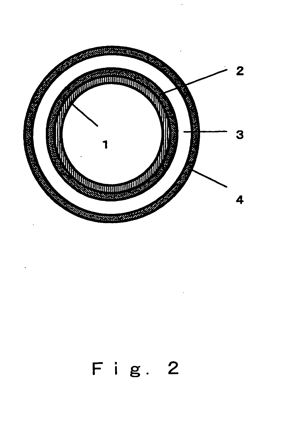
[0084] Zirconia stabilized with yttrium oxide was used as the solid electrolyte 3 having ion conductivity, and the shape thereof was that of a disk with a diameter of 20 mm and a thickness of 0.5 mm. The lower cathode 2 was formed by first producing a paste by adding an organic solvent to a mixed powder of an electron-conductive substance composed of platinum and an ion-conductive substance composed of zirconia stabilized with yttrium oxide, with the mixing ratio (volumetric ratio) being 60:40, and then applying this paste by screen printing to one side of the solid electrolyte 3 such that the surface area was approximately 1.8 cm2, and then heat treating this product at 1200° C. The upper cathode 1 was formed by first producing a paste by adding an organic solvent to a mixed powder of an electron-conductive substance composed of nickel oxide and nickel and an ion-conductive substance composed of zirconia stabilized with yttrium oxide, with the mixing ratio (volumetric ratio) being ...

example 2

[0086] A chemical reactor was produced in the same manner as in Example 1, except that the mixing ratio (volumetric ratio) of the electron-conductive substance and ion-conductive substance of the upper cathode 1 was changed to 35.0:65.0. The nitrogen oxide emission control characteristics of this chemical reactor were evaluated in the same manner as in Example 1, the results of which are given in Table 1.

example 3

[0087] A chemical reactor was produced in the same manner as in Example 1, except that the mixing ratio (volumetric ratio) of the electron-conductive substance and ion-conductive substance of the upper cathode 1 was changed to 44.6:55.4. The nitrogen oxide emission control characteristics of this chemical reactor were evaluated in the same manner as in Example 1, the results of which are given in Table 1.


PUM

PropertyMeasurementUnit
Temperatureaaaaaaaaaa
Ratioaaaaaaaaaa

Abstract

The present invention provides a chemical reactor with which nitrogen oxide emission control can be performed very efficiently at a low applied voltage when an excess of oxygen is present in a combustion exhaust gas. The present invention is a chemical reactor in which the upper cathode, lower cathode, and anode that make the chemical reactor are a mixture of an electron-conductive substance and an ion-conductive substance, and the electron-conductive substance and ion-conductive substance of the upper cathode are mixed in a specific ratio, which makes it possible to lower the applied voltage and reduce the power consumption of the chemical reactor, and is also a method for the emission control of nitrogen oxides in which this chemical reactor is used.

Description

TECHNICAL FIELD [0001] This invention relates to a chemical reactor for nitrogen oxide emission control, and more particularly relates to a chemical reactor for the efficient emission control of nitrogen oxides from a combustion exhaust gas in which there is an excess of oxygen that would hamper a chemical reaction for nitrogen oxide emission control, and to a method for nitrogen oxide emission control by using this chemical reactor. [0002] This invention also relates to a chemical reactor having a specific electrode layer, and more particularly relates to the structure of an electrochemical cell type of chemical reactor for subjecting a treatment substance to a chemical reaction, in which the structure of the path over which electrons are supplied for ionizing elements, and the path for excluding ionized elements from the catalyst reaction surface is optimized; for example, the emission control of nitrogen oxides from a combustion exhaust gas that contains oxygen can be performed e...

Claims


Application Information

Patent Timeline
IPC IPC(8): B01D53/94
CPCB01D2257/404B01D53/9431
Inventor AWANO, MASANOBUFUJISHIRO, YOSHINOBUHAE, JIN HWANGBREDIKHIN, SERGEIMATSUDA, KAZUYUKIKATAYAMA, SHINGOMIYATA, MOTOYUKIMAEDA, KUNIHIROHIRAMATSU, TAKUYASHIONO, OSAMU
Owner NAT INST OF ADVANCED IND SCI & TECH
Learn More