
High performance computer hard disk drive with a carbon overcoat and method of improving hard disk performance

a technology of hard disk drive and carbon overcoat, which is applied in the field of high-performance hard disk drive and method, can solve the problems of increasing the cost of doing business, inefficient use of back-up records, and inability to permanently lose important records, so as to achieve the effect of reducing costs, increasing hard disk drive capacity, and substantially reducing the volume of storage media

Inactive Publication Date: 2011-06-14
GALLEON INT CORP +1
View PDF13 Cites 13 Cited by
  • Summary
  • Abstract
  • Description
  • Claims
  • Application Information

AI Technical Summary

Benefits of technology

[0015]The primary objects of this invention are to improve the durability, increase the storage capacity and reduce the seek times of a hard disk drive. These objects are achieved by one or more of the following actions: (1) increasing the areal density of the data recording magnetic coating of a platter; (2) reducing the (magnetic spacing) operating gap between a head and platter; (3) eliminating landing zones, and (4) coating the head and platter with the “near frictionless” or similar coating of U.S. Pat. No. 6,548,173; and (5) mounting the drive in a sealed housing filled with an inert gas. These modifications further eliminate head crashes, eliminate corrosion, eliminate stiction, reduce cost and improve reliability. Costs are further reduced and reliability improved by eliminating head unloading technology (“HUT”) and laser texturing (“LT”) technology. As used herein, the term hard disk drive is intended to include optical and magnetic disk drives.
[0016]In a first aspect of the invention, the areal density of a hard disk drive is increased and the seek times reduced by replacing the coatings on hard disk platters with an ultra low friction and ultra low wear structurally amorphous carbon coating in an inert gas environment. There is no lubricant layer on the disk and the flying height is reduced to 0 nm (full contact) to 5.0 nm. In a like manner, mating bearing components in the hard disk drive spindle motor benefit from application of this ultra low friction and ultra low wear structurally amorphous carbon coating in an inert gas environment. Specifically, the bearing shaft and bushing or sleeve of the spindle motor are coated with the ultra-low friction amorphous carbon coating.
[0018]In a second aspect of the invention, hard disk drive capacity is increased and costs are reduced by eliminating landing zones, head unloading (“HUT”) and laser texturing” (“LT”) technology.
[0019]In a third aspect of the invention, the volume of storage media is substantially reduced by virtue of achieving disk storage on the order of terabits / in2. The multiplicity of disks in larger hard drives and servers can be reduced, as well as the complexity thereof.

Problems solved by technology

Head impacts [crashes] with platters, caused by power losses or low pressure at altitudes normally above 10,000 ft., can be catastrophic because important records can be permanently lost.
Consequently, time consuming back-up records are frequently made to protect data, thus increasing the cost of doing business.
Making back-up records is an inefficient use of valuable technical personnel.
Crashes also result in expensive drive replacements.
Pressure, temperature and humidity affect the operation of a hard disk drive.
If air pressure in a drive is too high, data will be improperly written and read.
Humidity over extended periods accelerates component corrosion.
Corrosion of the magnetic layer is adversely affected if the carbon overcoat is not dense or thick enough to provide full coverage.
When heads are parked for long periods of time, stiction can lead to hard drive failure and lost data.
Stiction can occur especially if a hard drive has been out of use for an extended period.
When the drive is powered up, the flying head can stick to the disk lubricant layer, potentially preventing the disk from rotating.
Wear, corrosion, manufacturing defects and head crashes are the major causes of hard drive failures.
When crashes occur, heads scrape and damage platters.
Impacts and contacts can occur during power down and power failures.
Landing zones reduce storage space, increase cost and make mechanical tolerance control more difficult.
Both technologies increase the cost, complexity and difficulty of manufacturing hard drives.
For increases in areal density, the carbon overcoat that protects the magnetic data recording layer must be thinner however, a thinner overcoat may expose the magnetic layer to corrosion because of pin holes.

Method used


Image

  • High performance computer hard disk drive with a carbon overcoat and method of improving hard disk performance
  • High performance computer hard disk drive with a carbon overcoat and method of improving hard disk performance
  • High performance computer hard disk drive with a carbon overcoat and method of improving hard disk performance

Examples


Embodiment Construction

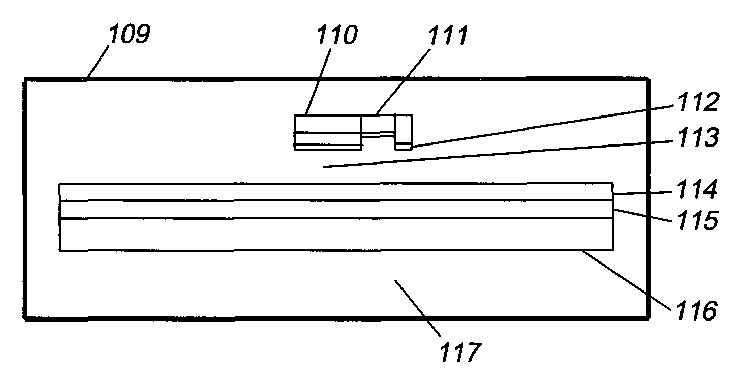
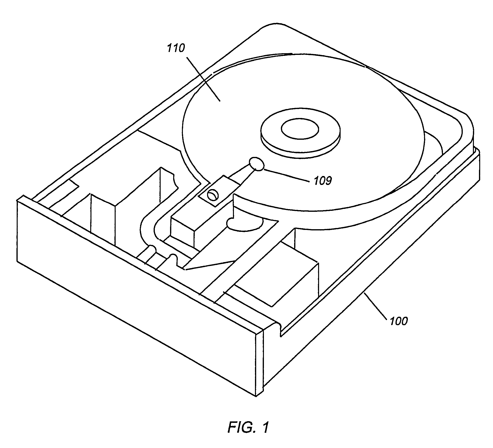
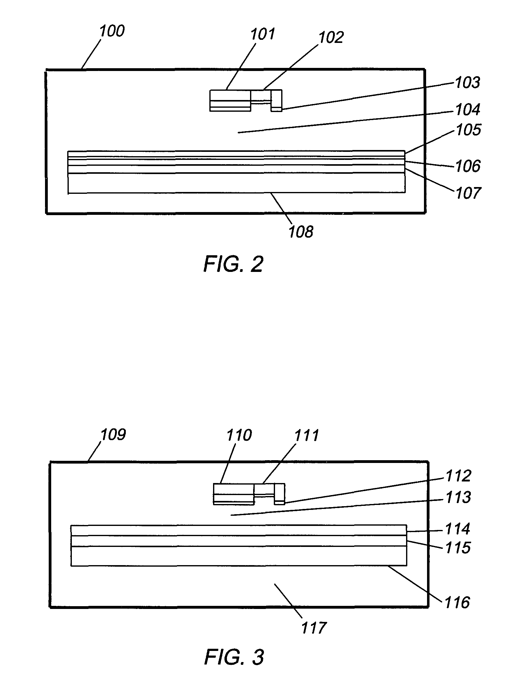
[0029]Referring now to the drawings wherein like numerals designate like and corresponding parts throughout the several views, as shown in FIG. 1, a hard disk drive consists of a housing 100 containing circular platters 110 which rotate in unison at high speeds past read-write heads 109. The heads 109 are supported on cushions of air above the platters 110. They write (record) digitized data on thin magnetic coatings that is read (retrieved) by sensors on the read-write heads 109.

[0030]The signal to noise ratio in a drive is proportional to the number of magnetic particles per bit to the one-half power, and progressively smaller grains with a higher disk coercivity are required for increases of areal density in every generation of disk drive. The spacing laws require a progressively decreasing magnetic spacing between a head and platter as areal density increases. This involves both reduced head flying heights as well as thinner protective coatings. In at least one embodiment of the...


PUM

PropertyMeasurementUnit
thicknessaaaaaaaaaa
thicknessaaaaaaaaaa
flying heightaaaaaaaaaa

Abstract

A high performance hard disk drive is disclosed in which a flying read / write head runs in contact or in near contact with a rotating platter. In this design there is no wear of the hard disk platter or flying head due to both head and platter being coated with an amorphous carbon that has an exceptionally low coefficient of friction in a sealed, inert gas environment. The overcoat contains carbon in the range between about 52 and 80 atomic percent and hydrogen in the range between about 20 to 48 atomic percent. There is no lubricant required in this design, which eliminates a significant cause of hard drive failure from oxidation of the lubricant, stiction and rippling of the lubricant. This contact method achieves a high areal density with no wear, within a robust, hermetically sealed environment.

Description

FIELD OF THE INVENTION[0001]This invention relates to computer storage devices and more particularly to a high performance hard disk drive and method.BACKGROUND OF THE INVENTION[0002]A hard disk drive stores digitally encoded data on circular plates, called platters. The platters are mounted on a spindle and rotate in unison at high speeds past read-write heads. The heads fly on sliders in close proximity to magnetic layers on the platters. Sensors write (record) and read (retrieve) the digitized data which is stored on the magnetic layers. The magnetic layers are protected with a thin carbon overcoat.[0003]Disk drives are mounted in sealed housings to protect them against dust, humidity, and other contaminants. The flying heads are supported on cushions of air only nanometers (flying height) above the platters. The platters must be free of contaminants and imperfections to maintain an extremely close spacing (flying height) between the heads and platters. Modern hard drives have fl...

Claims


Application Information

Patent Timeline
Patent Type & Authority Patents(United States)
IPC IPC(8): G11B5/40G11B5/72
CPCG11B5/102G11B5/255G11B5/8408G11B5/6005G11B5/3106G11B5/40G11B5/72G11B5/82G11B5/84G11B2220/2516
Inventor DORBECK, MARK A.SYKORA, FRANKERDEMIR, ALIERYILMAZ, OSMAN
Owner GALLEON INT CORP
Learn More