Tire inflation system

a technology of a tire inflation system and a tyre, which is applied in the direction of tyre parts, tyre-inflating valves, tyre measurements, etc., can solve the problems of large valves and actuators, high losses, and uncertain operation of the valves and actuators

Inactive Publication Date: 2011-06-21
MAGNA STEYR FAHRZEUGTECHN
View PDF12 Cites 16 Cited by
  • Summary
  • Abstract
  • Description
  • Claims
  • Application Information

AI Technical Summary

Benefits of technology

[0006]The foregoing object is obtained by providing a compressed-air generating system which has a first compressor and a second compressor, the first compressor provides compressed air at a medium pressure level to a first compressed-air system and the second compressor provides compressed air at a high pressure level to a second compressed-air system, with the wheel valves being connected to the first compressed-air system, and the pilot control valves being connected to the second compressed-air system. Since the pilot control valves are operated at a high and largely constant pressure level, the actuators for the wheel valves are small and operate reliably and quickly. They require only a very small amount of compressed air. The use of two compressors allows them to be designed specifically for the requirements and economically; the first compressor for the lower pressure level and higher feed rates, and the second compressor for the higher pressure level and lower feed rates. Because of the reservoir, the compressors also do not need to be designed for load peaks.
[0007]In a development of the invention, the second compressed-air system also supplies other loads, in particular pneumatic suspension bellows for pneumatic wheel suspension or level control. This results in better utilization of the second compressor, with pneumatic wheel suspension and the tire inflation system complementing one another well because of the low feed rates. In this case, at least one of the pneumatic suspension bellows can also be used as a pressure reservoir.
[0012]It is also within the scope of the invention for the control valves of the pneumatic suspension system and the electrically operated pilot control valves, which are fixed to the vehicle, for the wheel valves to be arranged in the vicinity of the wheels, so that the second compressed-air system has to feed only one (high-pressure) compressed-air line to each wheel. As a continuation of this idea, the electrically operated pilot control valves can be connected for flow purposes to the respective pneumatic suspension bellows such that they take the control air for the wheel valves therefrom. This results in a minimum number of compressed-air lines having to be installed in the vehicle.

Problems solved by technology

In addition, the wheel valves must be designed for the minimum system pressure of 2 bar, and their operation is uncertain with the low pressure differences that occur.
This necessitates very large valves and actuators, which cannot be accommodated in the wheel of a motor vehicle.
However, this requires a compressor which is designed for the maximum pressure, and is therefore large, thus incurring high losses.

Method used


Image

  • Tire inflation system
  • Tire inflation system
  • Tire inflation system

Examples


Embodiment Construction

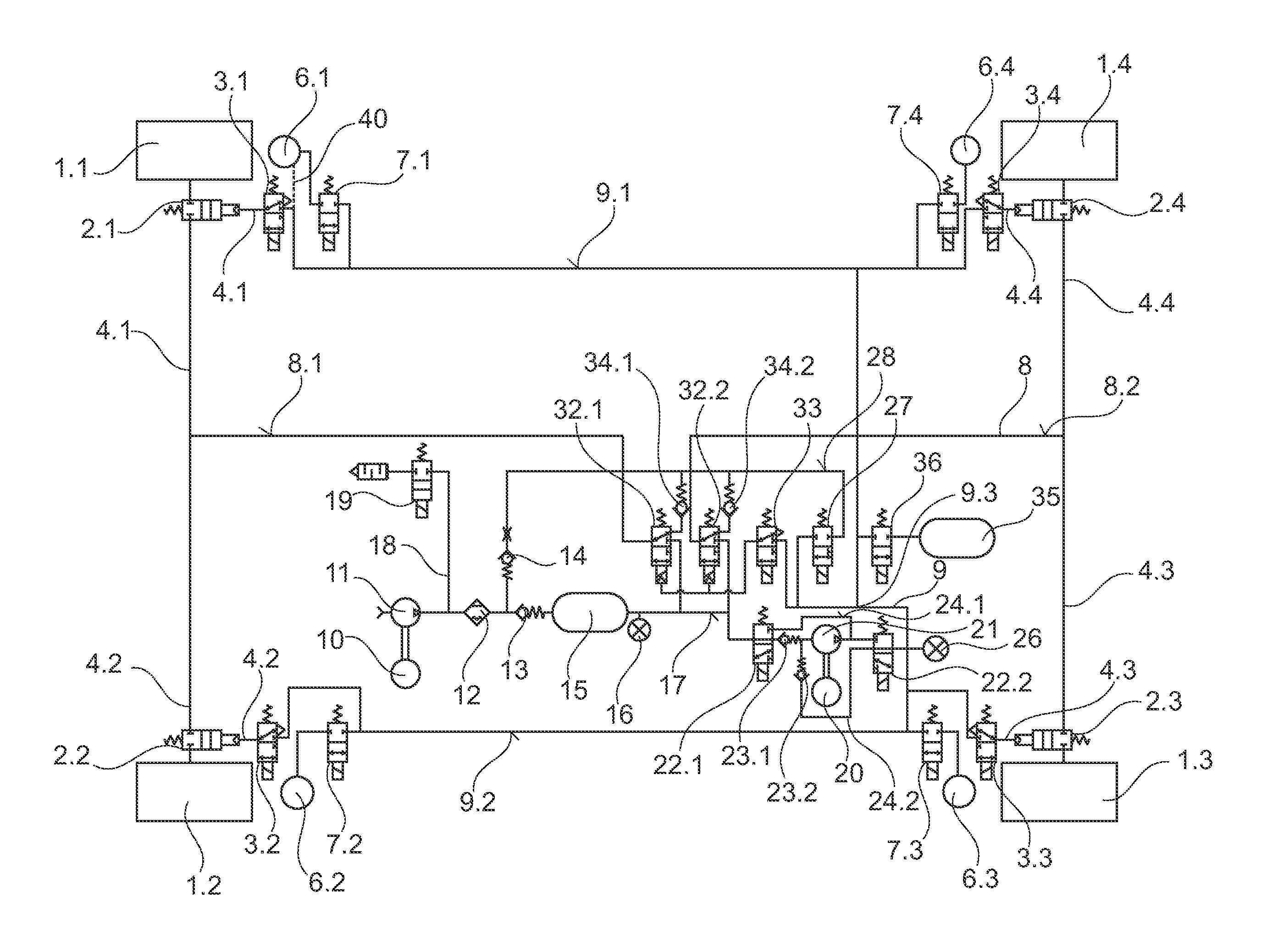
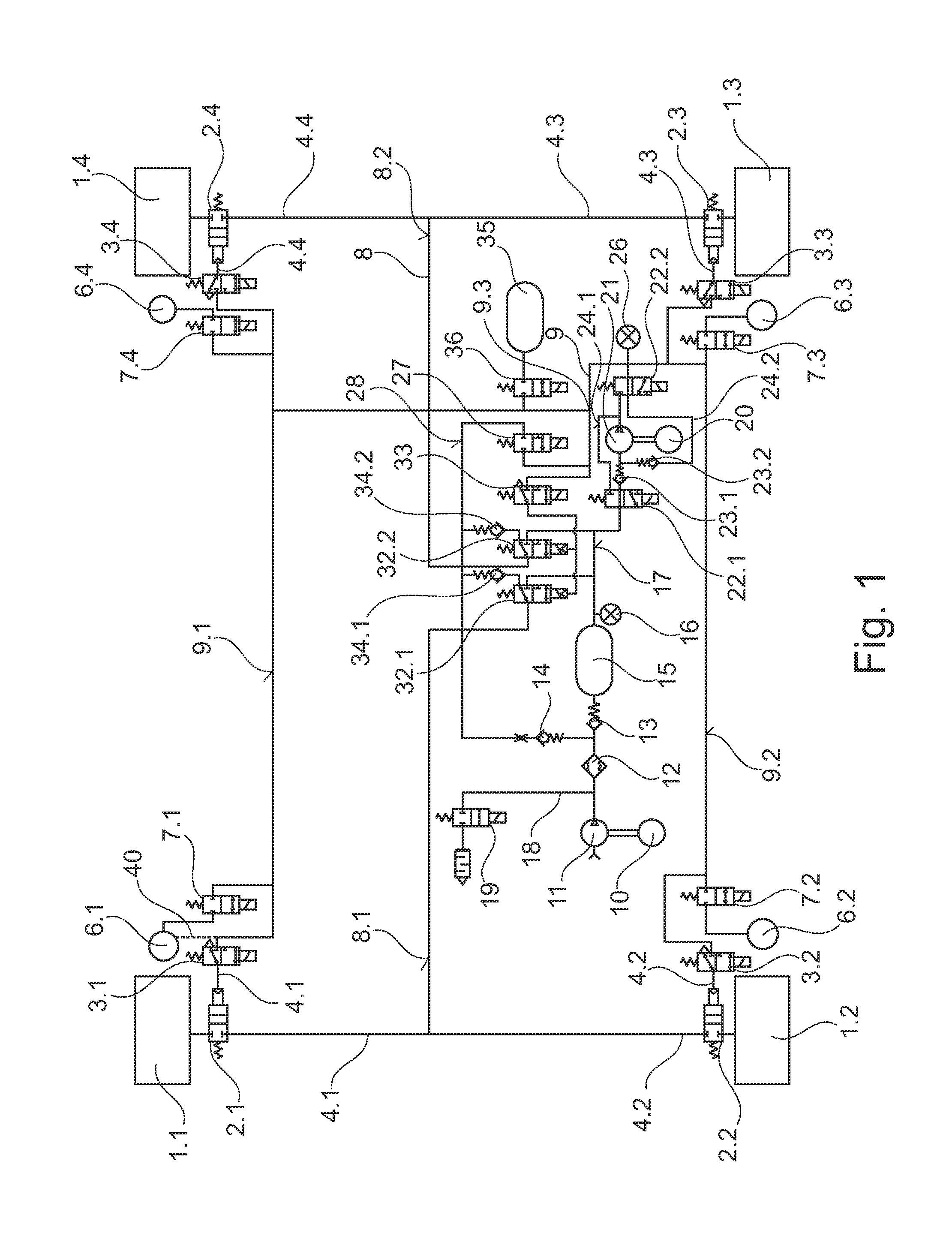
[0020]In FIG. 1, the wheels of a motor vehicle are annotated 1.1 to 1.4, wheel valves fitted to or in them are annotated 2.1 to 2.4, and associated pilot control valves are annotated 3.1 to 3.4. Wheel valves 2.1 to 2.4 and pilot control valves 3.1 to 3.4 are part of a tire inflation system. Pneumatic suspension bellows 6.1 to 6.4 and pneumatic suspension valves 7.1 to 7.4 are part of a pneumatic suspension system or a pneumatic level control system. The tire inflation system and pneumatic suspension system are connected to two compressed-air systems at different pressure levels.

[0021]The first compressed-air system produces a pressure of between 2 and 5 bar in the lines 8.1 and 8.2, which is passed via two-channel rotating introduction means 4.1 to 4.4 and the wheel valves 2.1 to 2.4 providing inflation air to the wheels, to be more precise to their tires. The second compressed-air system is at a pressure of, for example, 16 to 20 bar and comprises a pressure line 9, supplying the p...


PUM


Abstract

A tire inflation system comprising pneumatically controlled wheel valves that are situated in the wheels of a motor vehicle. An electrically actuated pilot valve that is fixed to the vehicle controls the respective wheel valves. To produce a small, low-cost, reliable tire inflation system, a first and a second compressor are provided. The first compressor supplies a first compressed air system with medium-pressure compressed air and the second compressor supplies a second compressed air system with high-pressure compressed air. The wheel valves are situated in the first compressed air system and the pilot valves are situated in the second compressed air system.

Description

BACKGROUND OF THE INVENTION[0001]The invention relates to a tire inflation system, comprising a compressed-air generating system, a compressed-air reservoir, a valve block and pneumatically driven wheel valves in the wheels of a motor vehicle, with an electrically operated pilot control valve which is fixed to the vehicle in each case driving at least one wheel valve.[0002]DE 40 09 687 A1 discloses a tire inflation system whose pressure generator is connected via axle valves to wheel valves which are not described in any more detail. In this case, the former control the latter by means of a pressure surge in the supply line leading to the wheel valve. Air let out from the tires is fed to the pressure generator, and from this to a pressure reservoir. This arrangement admittedly has the advantage of requiring only a single rotating transmission means into each of the wheels, although accurate and, in particular, operationally reliable, operation of the wheel valves is therefore imposs...

Claims


Application Information

Patent Timeline
Patent Type & Authority Patents(United States)
IPC IPC(8): B60C23/10
CPCB60C23/003B60C23/00305B60C23/00318B60C23/00354B60C23/00372
Inventor RUDOLF, MARKUSBERNT, AXELWINKLER, RENESCHWAMBERGER, MARTIN
Owner MAGNA STEYR FAHRZEUGTECHN
Why Eureka
Try Eureka