System for cooling a disc brake rotor and collecting brake pad waste

a technology of disc brake rotor and waste, which is applied in the direction of fluid actuated brakes, slack adjusters, braking elements, etc., can solve the problems of reducing the coefficient of friction needed for stopping power, releasing harmful particles into the atmosphere, and affecting the cooling effect of the rotor. , to achieve the effect of improving the airflow

Inactive Publication Date: 2011-06-21
GELB JOSEPH
View PDF85 Cites 9 Cited by
  • Summary
  • Abstract
  • Description
  • Claims
  • Application Information

AI Technical Summary

Benefits of technology

[0006]It is an object of the present invention is to provide a system which improves the airflow in a disc braking system by using impellers which are powered by a drive shaft that is rotated via a roller and is contacted with the brake rotor.
[0007]It is another object of the present invention to provide a housing that fits around a brake disc which holds the impellers, drive shaft, and filters. In an alternative embodiment, twin impellers could be used on either side of the rotor to maximize the air flow through the impellers.
[0009]It is another object of the present invention to provide another filter on the impeller housing outlet to capture the remaining particles as air is forced out of the impeller housing and onto the rotor to aid in cooling of the braking system.
[0010]In another exemplary embodiment, the housing can be designed to encompass the brake caliper so that the amount of brake residue captured and the air flow recycled on the brake rotor can be maximized.
[0011]It is another object of the present invention to provide pressure release valves near the air intake and outlet on the impeller housing. When either of these valves is activated, it will allow air to bypass the filters in the case they have been clogged. The bypassed air will be redirected to the brake rotor to aid in cooling.

Problems solved by technology

Additionally, as brake pads erode they release harmful particles into the atmosphere.
These harmful particles can also enter and pollute water streams.
This is because at high temperatures, the coefficient of friction needed for stopping power is reduced and brake performance is consequently diminished.
The waste that is released into the atmosphere from brake pads also creates multiple dilemmas.
This material is known as brake dust and can be problematic for two main reasons.
The first is that brake dust is highly corrosive and harmful to the environment.
The second problem is that the remainder of the brake dust that is not released into the atmosphere is deposited on the vehicle wheels.
The brake dust can be corrosive enough to burn through wheel coatings and leave expensive wheels damaged and unsightly.
None of the above referenced devices addresses all the problems associated with brake pad waste.

Method used


Image

  • System for cooling a disc brake rotor and collecting brake pad waste
  • System for cooling a disc brake rotor and collecting brake pad waste
  • System for cooling a disc brake rotor and collecting brake pad waste

Examples


Embodiment Construction

[0023]It will be readily understood that the components of the present invention, as generally described herein, could be arranged and designed in a wide variety of different formulations. Thus, the following more detailed description of the embodiments of the compositions or formulations of the present invention are not intended to limit the scope of the invention, as claimed, but are merely representative of the presently preferred embodiments of the invention.

[0024]Reference will now be made in detail to the presently preferred embodiments of the invention, examples of which are illustrated in the accompanying drawings, wherein like reference numerals refer to like elements throughout.

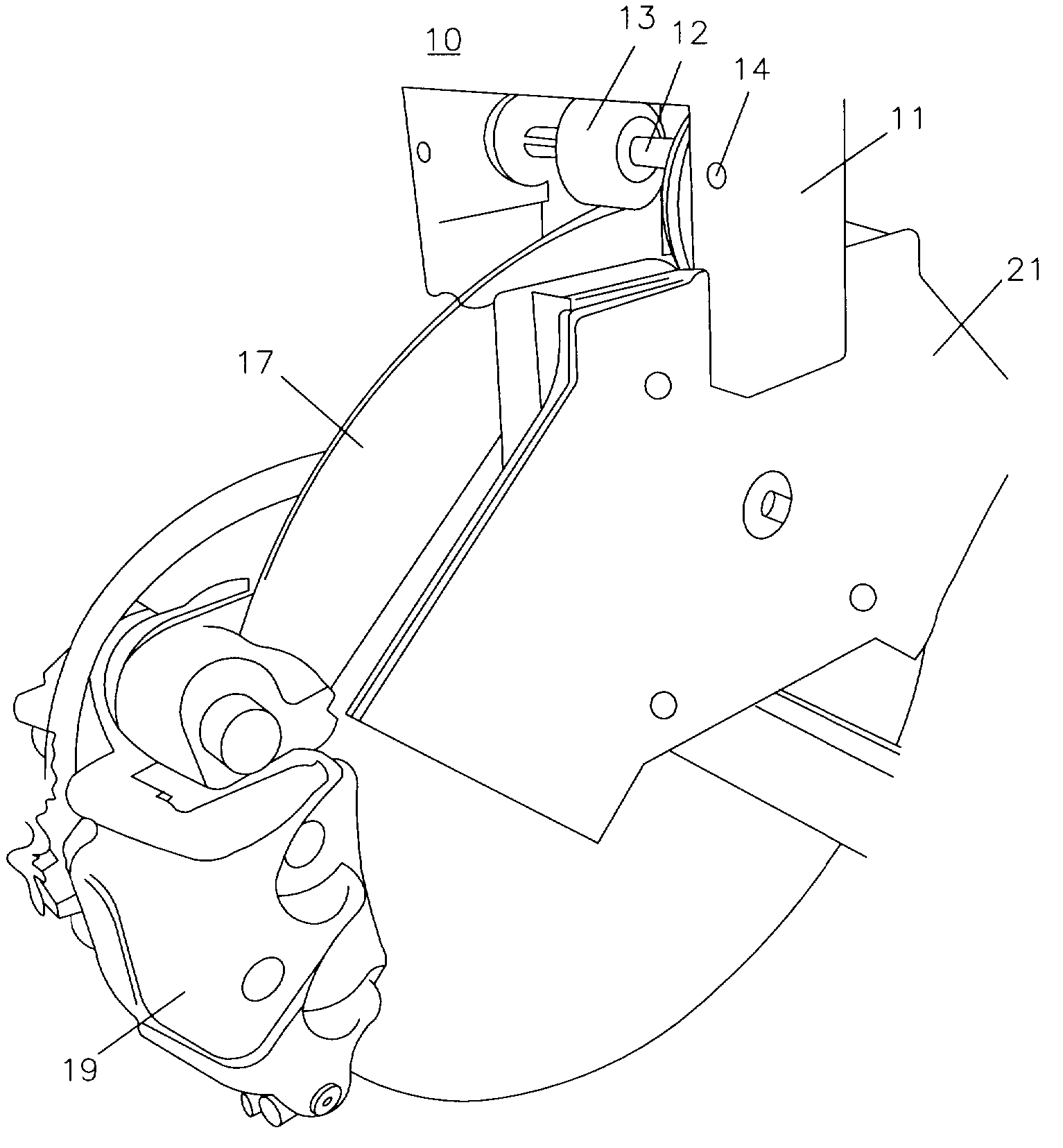
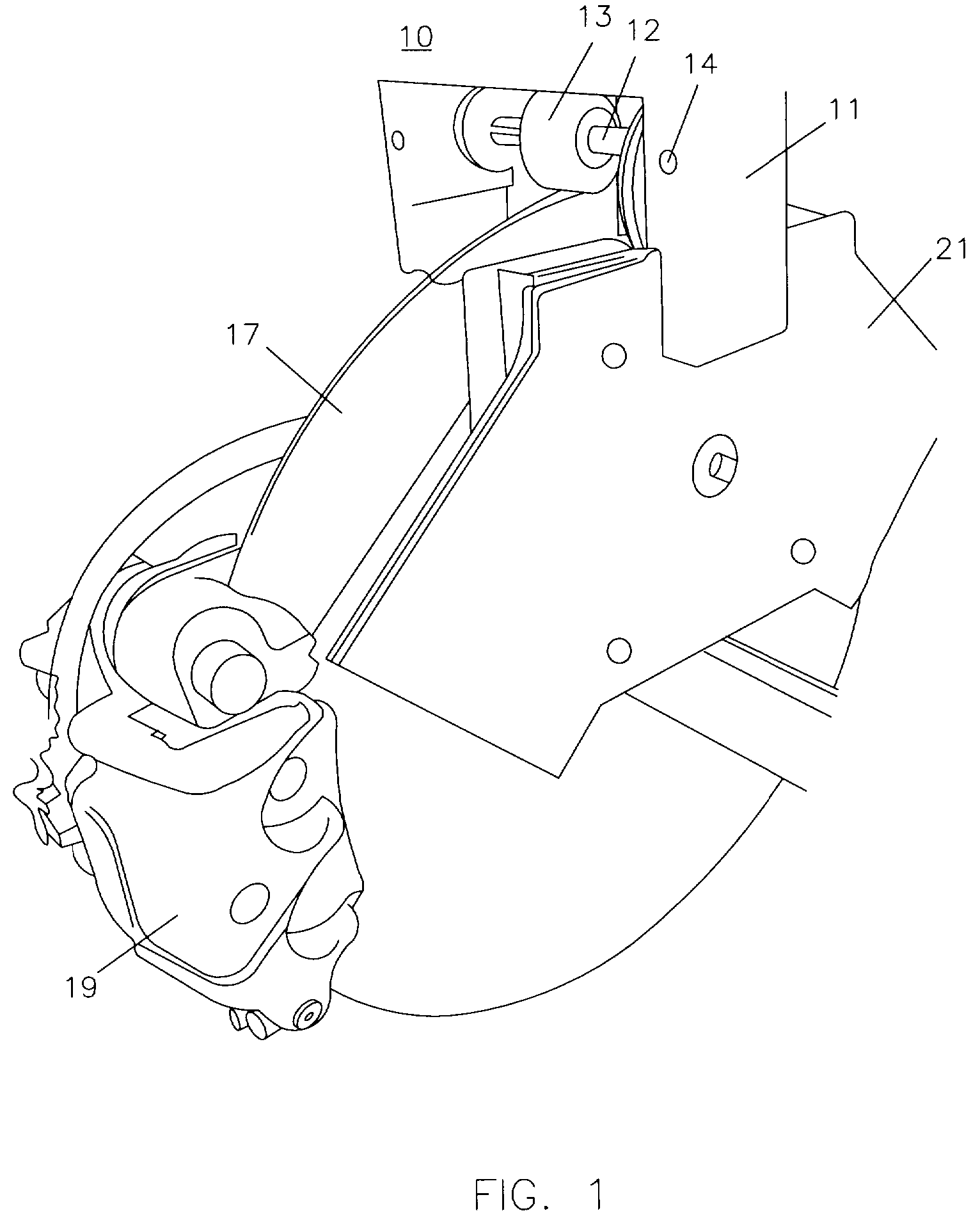
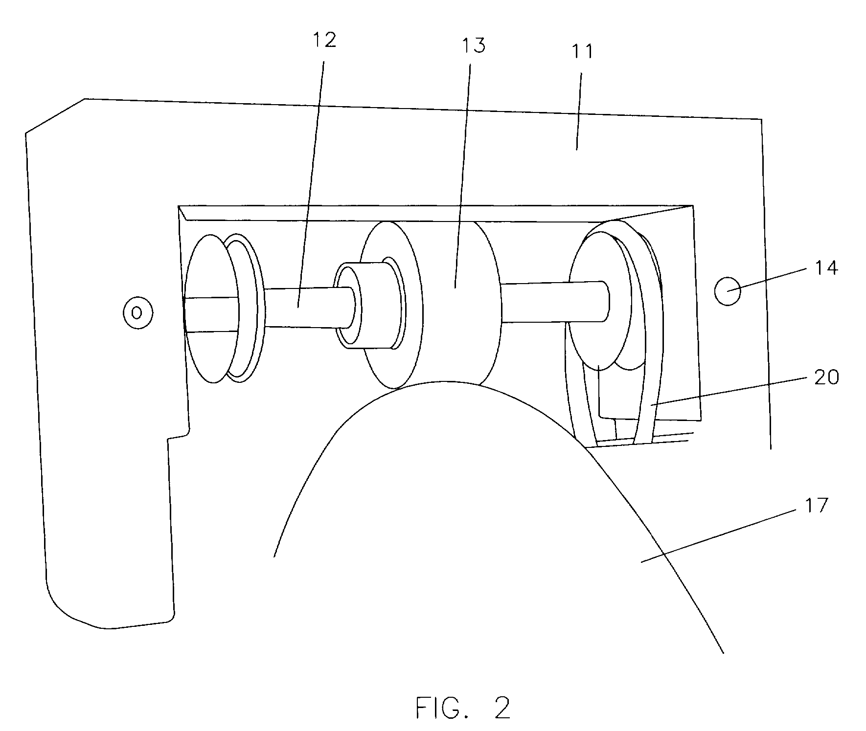
[0025]Referring to FIG. 1, the system 10 for increasing the airflow in a disc brake system and collecting brake pad waste is shown. The system 10 is contained in a main housing 11. The housing 11 is attached to a baffle plate 16 that is found in the braking system of many automobiles. In other embod...


PUM


Abstract

The present invention is a system which improves the airflow in a disc braking system by using impellers which are powered by a drive shaft that is rotated via a roller that is contacted with the brake rotor. A housing is provided that fits on a brake disc which holds the impellers, drive shaft, and filters. In an alternative embodiment, twin impellers could be used on either side of the rotor to maximize the air flow through the impellers. It is another object of the present invention to provide an impeller shroud housing that has an inlet to allow air to enter the shrouding. There is a mesh filter on the inlet which can capture particles as air is forced into the shrouding. Another filter on the shroud housing outlet to capture the remaining particles as air is forced out of the shroud housing and onto the rotor to aid in cooling of the braking system.

Description

FIELD OF THE INVENTION[0001]The present invention is directed towards a system for collecting the waste discharged from brake pads used in standard disc braking systems. More specifically, the invention discloses a system utilizing impellers, powered by the momentum of the brake rotor, to direct brake pad waste to a collection area.BACKGROUND OF THE INVENTION[0002]Disc brake systems are the most common form of braking mechanisms used today for vehicle wheels and most specifically for mass produced automobiles. Disc braking systems work by utilizing brake pads which are compressed against a rotor (also called a disc) to slow down a vehicle's wheels. As a by-product of this system, a large amount of heat is released as the kinetic energy from the wheel momentum is converted by the friction created by the brake pads. Additionally, as brake pads erode they release harmful particles into the atmosphere. These harmful particles can also enter and pollute water streams. The present inventi...

Claims


Application Information

Patent Timeline
Patent Type & Authority Patents(United States)
IPC IPC(8): F16D65/847
CPCF16D55/00F16D65/0031F16D2065/787
Inventor GELB, JOSEPH
Owner GELB JOSEPH
Why Eureka
Try Eureka