Self-contained self-elevating platform lift

a self-elevating platform and self-elevating technology, which is applied in the direction of lifting equipment, curtain suspension devices, filing appliances, etc., can solve the problems of similar problems and objects are too heavy for a single person, and achieve the effects of easy and quick installation, simple design, and low cos

Inactive Publication Date: 2011-06-21
TAYLOR JAMES E +1
View PDF64 Cites 14 Cited by
  • Summary
  • Abstract
  • Description
  • Claims
  • Application Information

AI Technical Summary

Benefits of technology

[0008]The particular gear-reducer selected is a low-speed, high-torque (high-ratio) “worm” gear type which is coupled to a high-speed, low-torque electric motor, producing a gear-motor combination, which is compact and efficient. The gear-motor combination provides two important features and benefits: it is “self-locking” when power is OFF, i.e., it cannot be rotated; and dangerous “free-wheeling” is eliminated. Because it is not “free-wheeling,” there is no need for a brake. The gear of the worm-gear reducer is keyed to a single continuous drive shaft. The single continuous drive shaft goes through the reducer and supports four cable sheaves, which are mounted adjustably thereon and locked to take in or feed out the lift's cables as the shaft rotates. A gear motor reducer is generally centrally mounted firmly to, and is supported by and within, the enclosure. Since two of the lift lines pull horizontally in one direction and the other two pull substantially horizontally in the opposite direction, the lift line loads cancel each other, such that the reducer experiences only torsion. This torsion is reacted by minor differences in the loads on each of the two pairs of lift lines at opposite ends of the enclosure. Loads will reverse when the direction of the travel of the lift is reversed. Each pair of lift lines are then directed around a corresponding pair of pulleys at each end of the enclosure and vertically upward to the floor above the opening.
[0010]The lift module is, therefore, self-contained and self-elevating in that the objects to be lifted, as well as the platform and enclosure, including the entire powered lifting mechanism, is intact to support and lift the objects. Numerous advantages can be appreciated when operating, adjusting, trouble-shooting, or maintaining the above-described lift.
[0011]The lift module provides a most simple design having a minimum number of parts and, therefore, minimum cost. This is accomplished while still adequately meeting design specifications, i.e., to safely lift objects falling within maximum weight and size limits, within given time frames to and from specific heights. The only items not located in the enclosure are: vertically extending lift lines, two at each end of the enclosure; lift line end supports located at the attic floor; and in one embodiment, a flexible electrical control cable and control box.
[0012]An important feature and benefit of this particular design is that the lift line ends extending vertically above and supporting the lift module are easily and quickly installed, or uninstalled, in the attic floor. This eliminates anything being permanently installed and operating in the opening between the joists and headers, or above the floor opening. The result is an efficient, clean, and inexpensive system.

Problems solved by technology

This can be quite dangerous.
Often times, the objects are too heavy for a single person to carry the objects up the set of stairs.
Similar problems exist for other areas in which to store personal items.

Method used


Image

  • Self-contained self-elevating platform lift
  • Self-contained self-elevating platform lift
  • Self-contained self-elevating platform lift

Examples


Embodiment Construction

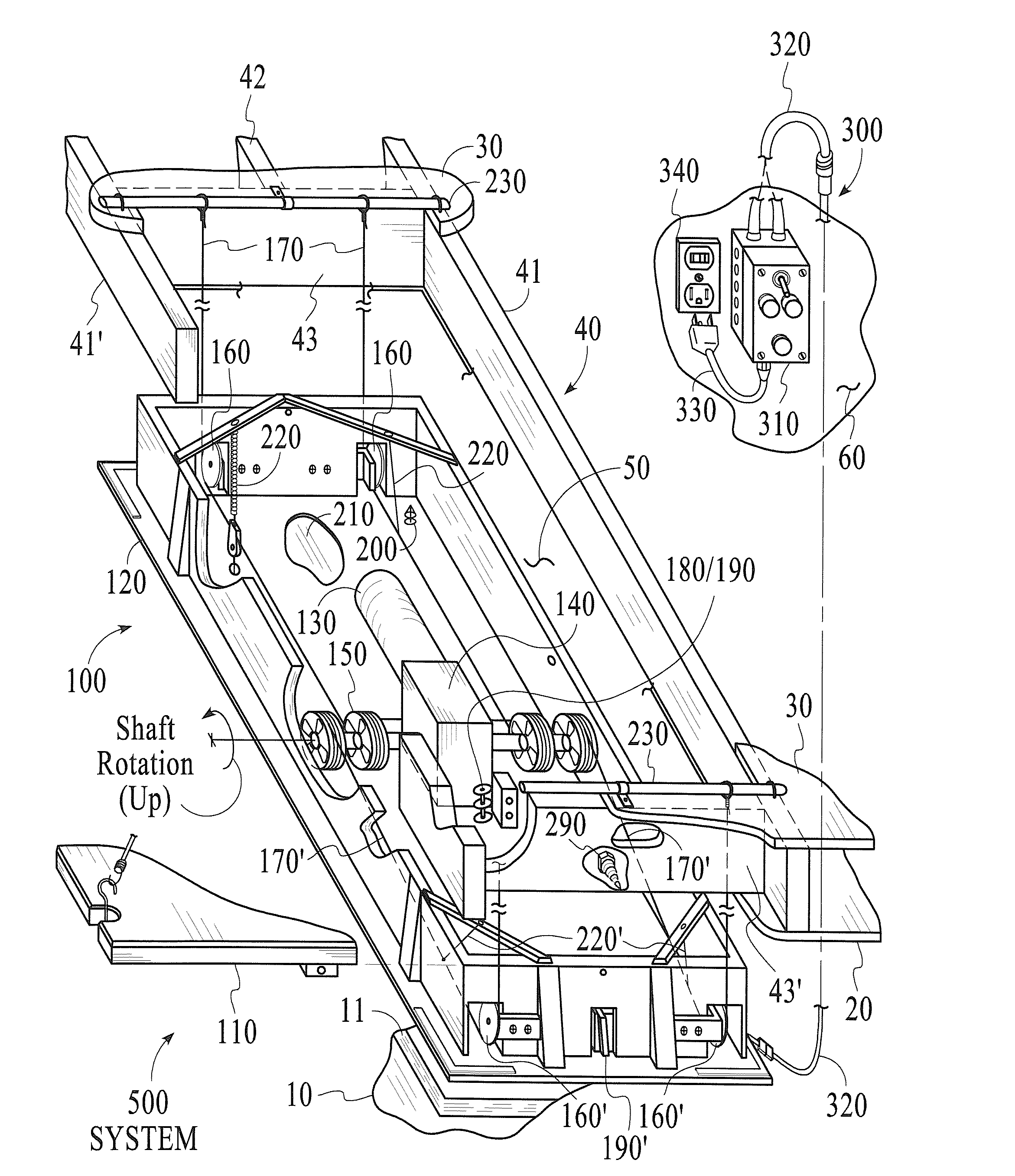
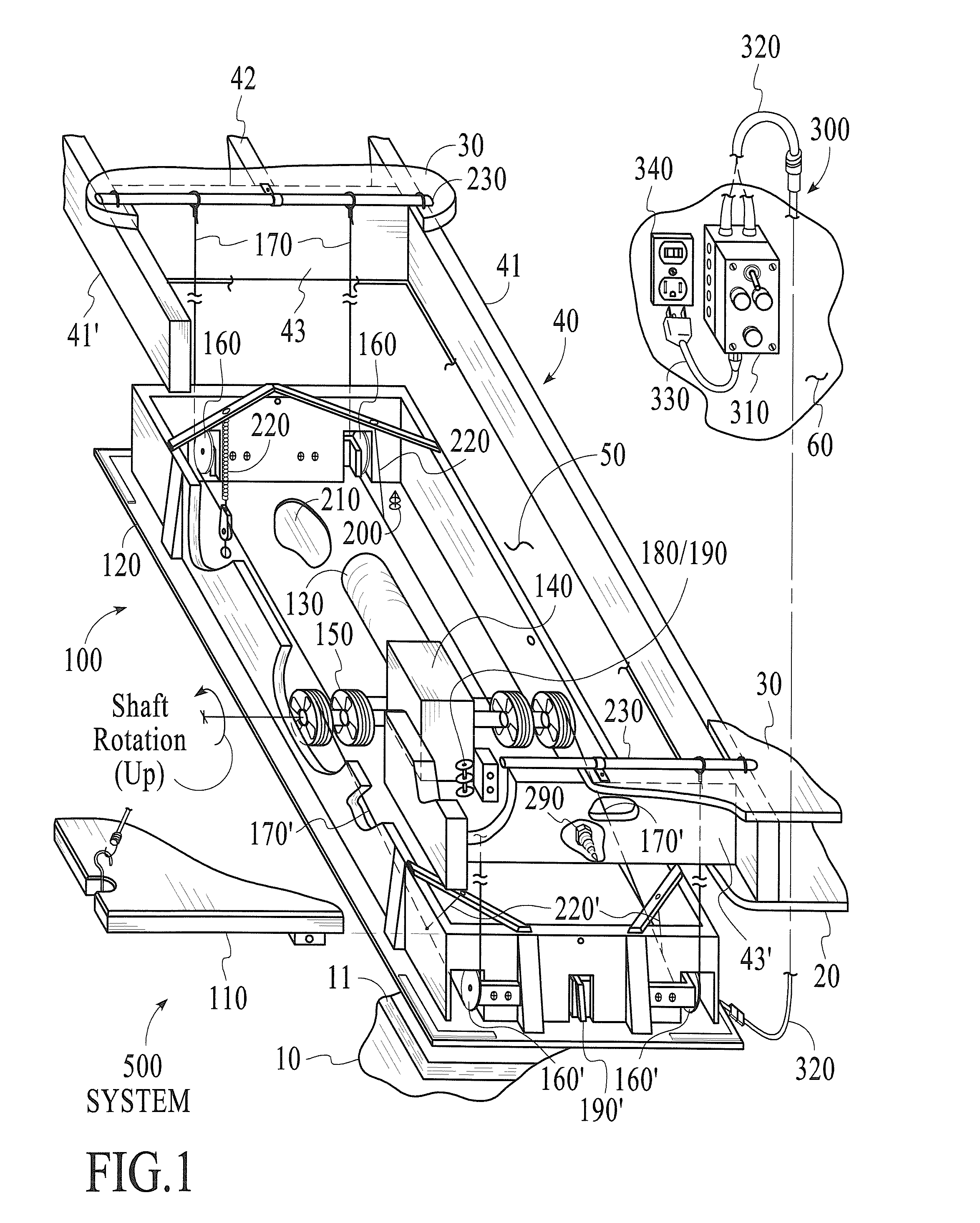
[0037]The isometric pictorial drawing of system 500 in FIG. 1 is presented to enable one quickly to view clearly the simplicity of lift module 100, showing a minimum number of parts to achieve the intended purpose of the invention. Module 100 includes platform 110, enclosure 120, and power lifting mechanism 130. Power mechanism 130 consists of gear-motor 140, single shaft and sheaves assembly 150, two pulley installations 160 and 160′, two lift line installations (hereinafter referred to as “wire cable installations”170 and 170′), lower travel limit installation 180 with lower limit switch installation 190, and upper travel limit installation with upper limit switch installation 190′ at one end of enclosure 120. Also related to the power lifting mechanism 130 of module 100 is the electrical system 300. It readily can be seen that the entire power lifting mechanism 130 is within the enclosure 120 and is covered by, and below, the platform 110. Therefore, the module 100 is self-contai...


PUM


Abstract

In one embodiment, a self-elevating platform lift for moving objects between a first level and a vertically-elevated second level is provided. The platform lift comprises: (A) a platform for supporting the objects; (B) a plurality of lift lines for connection at the second level and for moving the platform; and (C) a motor connected to move with the platform and wherein the motor operably is connected to the lift lines for moving the platform between the first and second levels while being supported by the lift lines. In another embodiment, a lift installation is provided for moving objects between a first level and a vertically-elevated second level comprising: (A) a platform for supporting the objects; (B) a plurality of lift lines fixed at one end to extend downward from the second level for moving the platform; and (C) a motor connected to move with the platform and wherein the motor operably is connected to the lift lines for use in moving the platform between the first and second levels while being supported by the lift lines.

Description

CROSS-REFERENCE TO RELATED APPLICATIONS[0001]This application claims the priority of U.S. Provisional Patent Application Ser. No. 61 / 190,329, filed Aug. 28, 2008FIELD OF INVENTION[0002]The field of the invention is directed to a self-contained, self-elevating platform for lifting objects to and from an elevated area.BACKGROUND OF THE INVENTION[0003]Houses often contain an attic in which to store personal belongings. An attic is normally accessed via a set of stairs. In order to place objects in the attic, a person must pull on a cord or rope, which is attached to the set of stairs, and then navigate up the stairs with a box or objects in hand. This can be quite dangerous. Often times, the objects are too heavy for a single person to carry the objects up the set of stairs. Similar problems exist for other areas in which to store personal items. For example, a garage or shed can contain a similar storage area which has an upper floor space and a set of stairs.[0004]Therefore, there is...

Claims


Application Information

Patent Timeline
Patent Type & Authority Patents(United States)
IPC IPC(8): B66D1/36
CPCB66D1/26B66D1/12
Inventor TAYLOR, JAMES E.TAYLOR, TOMMY W.
Owner TAYLOR JAMES E
Why Eureka
Try Eureka