
Hairpin microstrip bandpass filter

a bandpass filter and microstrip technology, applied in waveguides, basic electric elements, waveguide type devices, etc., can solve the problems of filtering over a foot in length, rods can become quite large, and circuit to circuit variations larg

Active Publication Date: 2011-06-21
HARRIS STRATEX NETWORKS
View PDF15 Cites 4 Cited by
  • Summary
  • Abstract
  • Description
  • Claims
  • Application Information

AI Technical Summary

Benefits of technology

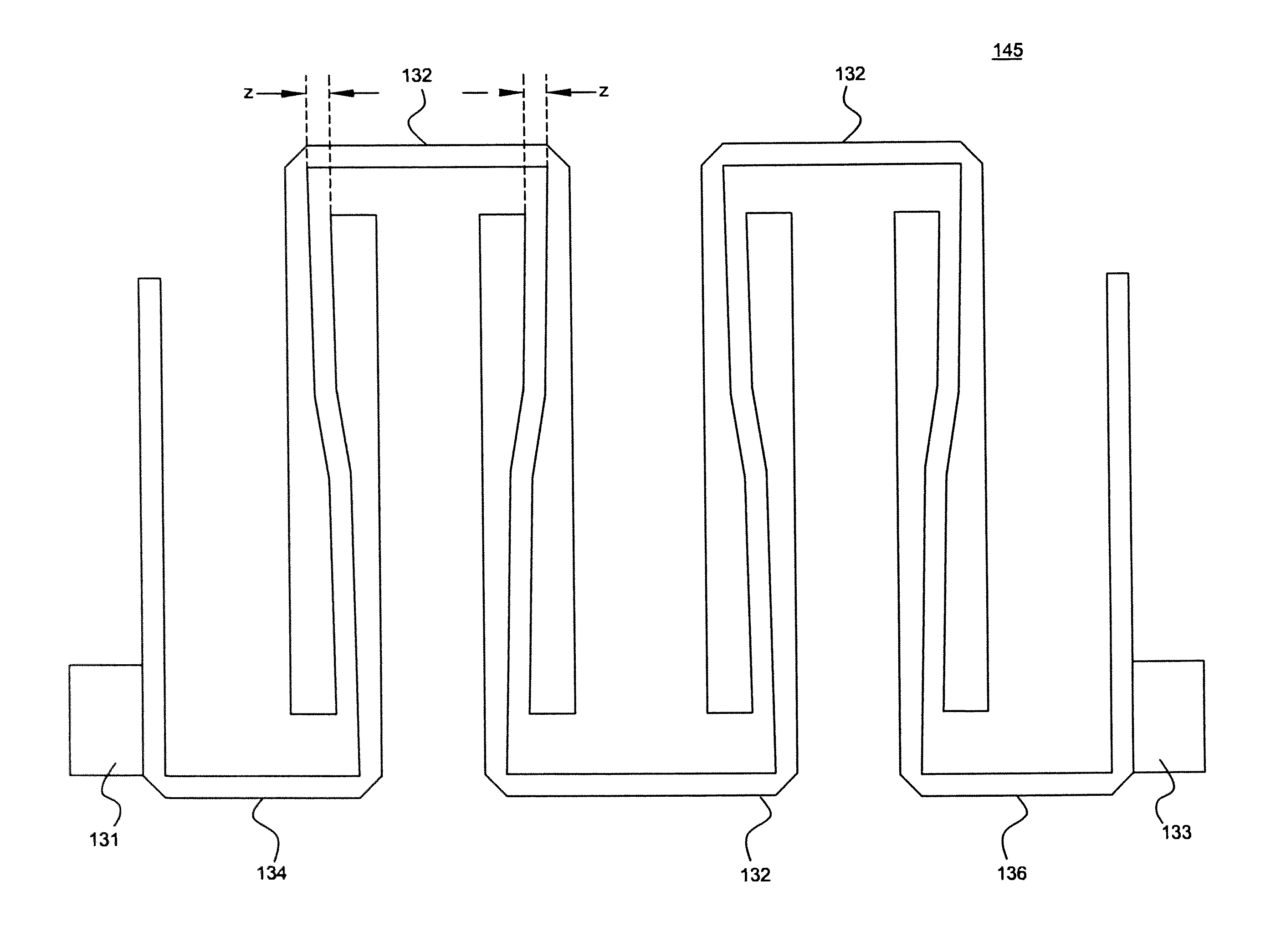
"The patent describes a type of filter made up of multiple \"hairpin\" resonators that are connected at one end in a \"U\" shape. The filter has three resonators, with one of them being connected to a first feed point, another being connected to a second feed point, and the third resonator being connected between the first and second resonators. The end portion of one of the legs of one of the resonators is tapered, making it thicker at one end than at the other end. The technical effect of this design is that it provides a more efficient and effective filter for transmitting signals in a specific frequency range."

Problems solved by technology

However, the use of separate elements has proved to be difficult to manufacture, resulting in large circuit to circuit variations.
Accordingly, the bars or rods can become quite sizeable, often being several inches long, resulting in filters over a foot in length.
Again, the size of these filters can become quite large.
These materials have an inherent high loss, and the circuits formed therefrom possess varying degrees of loss.
This is particularly true of HTSC filters where the available size of usable substrates is generally limited.
In the case of narrow-band microstrip filters (e.g., bandwidths of approximately 2 percent) this size problem may become quite severe.
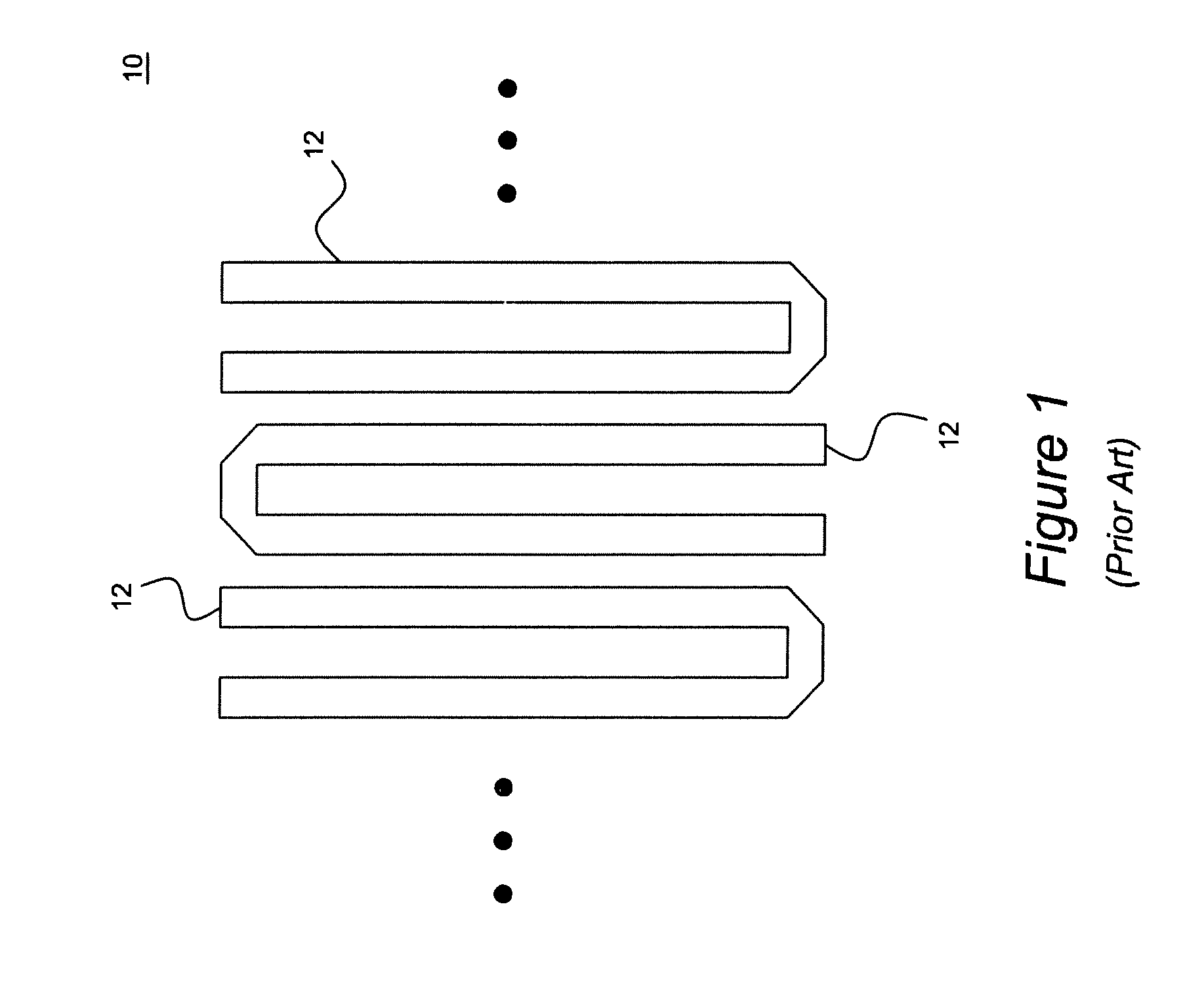
However, in the case of narrow-band filters, particularly for microstrip filters on a high-dielectric substrate, this structure is undesirable as it may require quite large spacings between the resonators 12 to achieve a desired narrow bandwidth.
If the resonators have sufficiently large capacitive loading, these resonator structures can be quite small, but, typically, their Q is inferior to that of a full hairpin resonator.
Also, there will normally be no resonance effect in the region between the resonators so that the coupling mechanism cannot be used to generate poles of attenuation beside the passband in order to enhance the stopband attenuation.
It has proved to be especially difficult to substitute HTSC in conventional circuits to form superconducting circuits without severely degrading the intrinsic Q of the superconducting films.
Among the problems encountered are radiative losses and tuning, which remain despite the clear desirability of improved filters.
Also, power limitations arise in certain structures.

Method used


Image

  • Hairpin microstrip bandpass filter
  • Hairpin microstrip bandpass filter
  • Hairpin microstrip bandpass filter

Examples


Embodiment Construction

[0033]With reference to the figures where like elements have been given like numerical designations to facilitate an understanding of the present subject matter, the various embodiments of a method and apparatus for filtering a selected frequency band are herein described.

[0034]FIG. 4 is an illustration of a microstrip filter according to an embodiment of the present subject matter. With reference to FIG. 4, a microstrip filter 40 comprises a plurality of hairpin microstrip resonators each having two substantially rectangular legs connected at one end and generally configured in a “U” shape. A first of the microstrip resonators 44 may be operatively connected to a first feed point 41 and a second of the microstrip resonators 46 may be operatively connected to a second feed point 43. The first feed point 41 may provide a signal (not shown) to the filter 40 and the second feed point 43 may provide a filtered output signal (not shown) to external components. Of course, the second feed ...


PUM


Abstract

A microstrip filter having a plurality of hairpin microstrip resonators each having two substantially rectangular legs connected at one end and generally configured in a “U” shape. The microstrip filter may comprise a first of the plural resonators operatively connected to a first feed point, a second of the plural resonators operatively connected to a second feed point, and a third of the plural resonators operatively connected between the first and second resonators where an end portion of one of the legs of one of the resonators is tapered so that a thickness of the one leg is greater at one end of the one leg than at another end of the one leg.

Description

CROSS REFERENCE TO RELATED APPLICATIONS[0001]This application is a divisional application of and seeks benefit and priority to U.S. nonprovisional application Ser. No. 11 / 600,167, now U.S. Pat. No. 7,688,162, entitled “Hairpin Microstrip Bandpass Filter,” filed Nov. 16, 2006, and issued Mar. 30, 2010 which is hereby incorporated by reference herein.BACKGROUND[0002]Filters are commonly utilized in the processing of electrical signals. For example, in communications applications, such as microwave applications, it is desirable to filter out the smallest possible passband and thereby enable dividing a fixed frequency spectrum into the largest possible number of bands.[0003]Historically, filters have fallen into three broad categories. First, lumped element filters utilize separately fabricated air wound inductors and parallel plate capacitors, wired together to form a filter circuit. These conventional components are relatively small compared to the wave length, and thus provide a comp...

Claims


Application Information

Patent Timeline
Patent Type & Authority Patents(United States)
IPC IPC(8): H01P1/203
CPCH01P1/203
Inventor SOORA, SHRUTHI
Owner HARRIS STRATEX NETWORKS
Learn More