Microstrip filter of short length

A technology of filter and filter response, which is used in waveguide-type devices, electrical components, multi-terminal pair networks, etc.

Inactive Publication Date: 2006-04-19
卡莱汉系乐有限公司
View PDF1 Cites 4 Cited by
  • Summary
  • Abstract
  • Description
  • Claims
  • Application Information

AI Technical Summary

Problems solved by technology

Since size is critical for the electrical response in the case of m

Method used


Image

  • Microstrip filter of short length
  • Microstrip filter of short length
  • Microstrip filter of short length

Examples


Embodiment Construction

[0024] In general, the invention relates to filters in the high frequency range, ie frequencies above 500 MHz.

[0025] The filters shown in the examples of embodiments for the frequency range of 1.8 to 2.3 GHz are provided. In an HF transmitter for digital video data (DVB-RCS), a QPSK-modulated signal will be generated in which unwanted sidebands are attenuated by at least 60 dBc. The filter used is variable in the range of 500MHz.

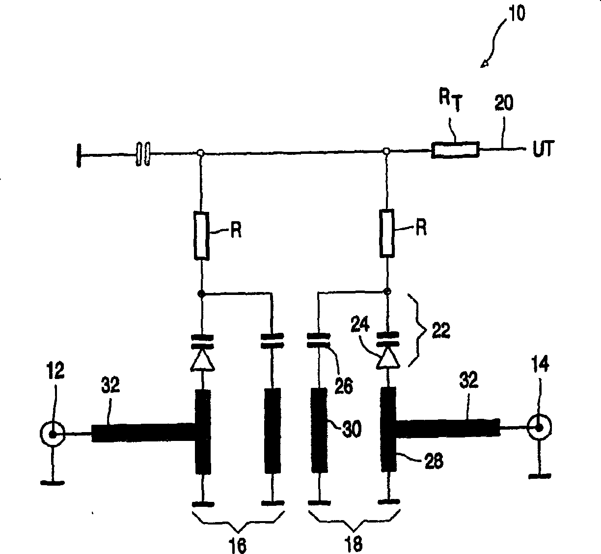
[0026] figure 1 A diagram showing a first filter circuit 10 provided for this purpose. The figure is a partial geometric diagram showing in principle the shape and relative arrangement of the microstrips used.

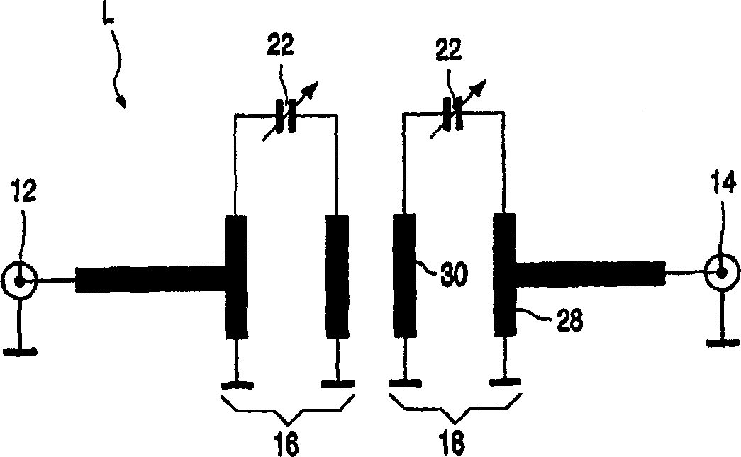
[0027] Filter 10 has an input 12 and an output 14 . The first resonator 16 is connected to the input 12 . The second resonator 18 is connected to the output 14 . The resonators 16, 18 are designed to be symmetrical to each other and are electromagnetically coupled to each other. The filter 10 has a connection 20 for a variable volt...


PUM


Abstract

A description is given of a high frequency filter comprising microstrips. The filter comprises at least two resonators (16, 18) which each have, as frequency-determining elements, a first straight microstrip section (28) and a second straight microstrip section (30), which are parallel next to each other, and also a capacitor assembly (22). In each resonator the capacitor assembly is connected between first ends of the microstrip sections and each resonator is exclusively connected to ground at the second ends of the microstrip sections. In each resonator (16, 18) the sum of the two microstrip sections acts as inductive lement. The resonators (16, 18) therefore act in the same manner as a resonator having a single microstrip, the length of which corresponds essentially to the sum of the lengths of the first microstrip section (28) and the second microstrip section (30). This construction of a filter allows a shorter design compared to conventional filter structures.

Description

technical field [0001] The present invention relates to high frequency microstrip filters. Background technique [0002] In the high frequency range, the use of microstrips in filter structures is known. A microstrip is a strip-shaped flat conductor attached to an insulating substrate. By suitable selection of the corresponding parameters (dimensions, dielectric constant of the substrate material, etc.), it is possible to make the microstrip have a desired impedance response at the frequencies involved. To construct filter structures, it is known to construct resonators consisting of microstrips and capacitors. Microstrips parallel to each other and spaced apart by a certain distance are electromagnetically coupled. By appropriate selection of the values ​​and dimensions of these elements and their mutual arrangement, desired filter characteristics can be set. [0003] Such filters are used, for example, in HF (high frequency) transmitters or receivers. In this case, fo...

Claims


Application Information

Patent Timeline
IPC IPC(8): H03H7/01
CPCH03H7/0123H01P1/203H03H7/01
Inventor E·齐利欧卡斯
Owner 卡莱汉系乐有限公司
Why Eureka
Try Eureka