
Running control system for vehicle

a control system and vehicle technology, applied in process control, machine control, reradiation, etc., can solve the problems of radar devices that cannot be stopped while the vehicle is stopped, radar devices that radar devices that may overheat and have a reduced durability, and devices with the reduced transmission output are prone to lose sight of the preceding

Inactive Publication Date: 2011-06-21
HONDA MOTOR CO LTD
View PDF43 Cites 2 Cited by
  • Summary
  • Abstract
  • Description
  • Claims
  • Application Information

AI Technical Summary

Benefits of technology

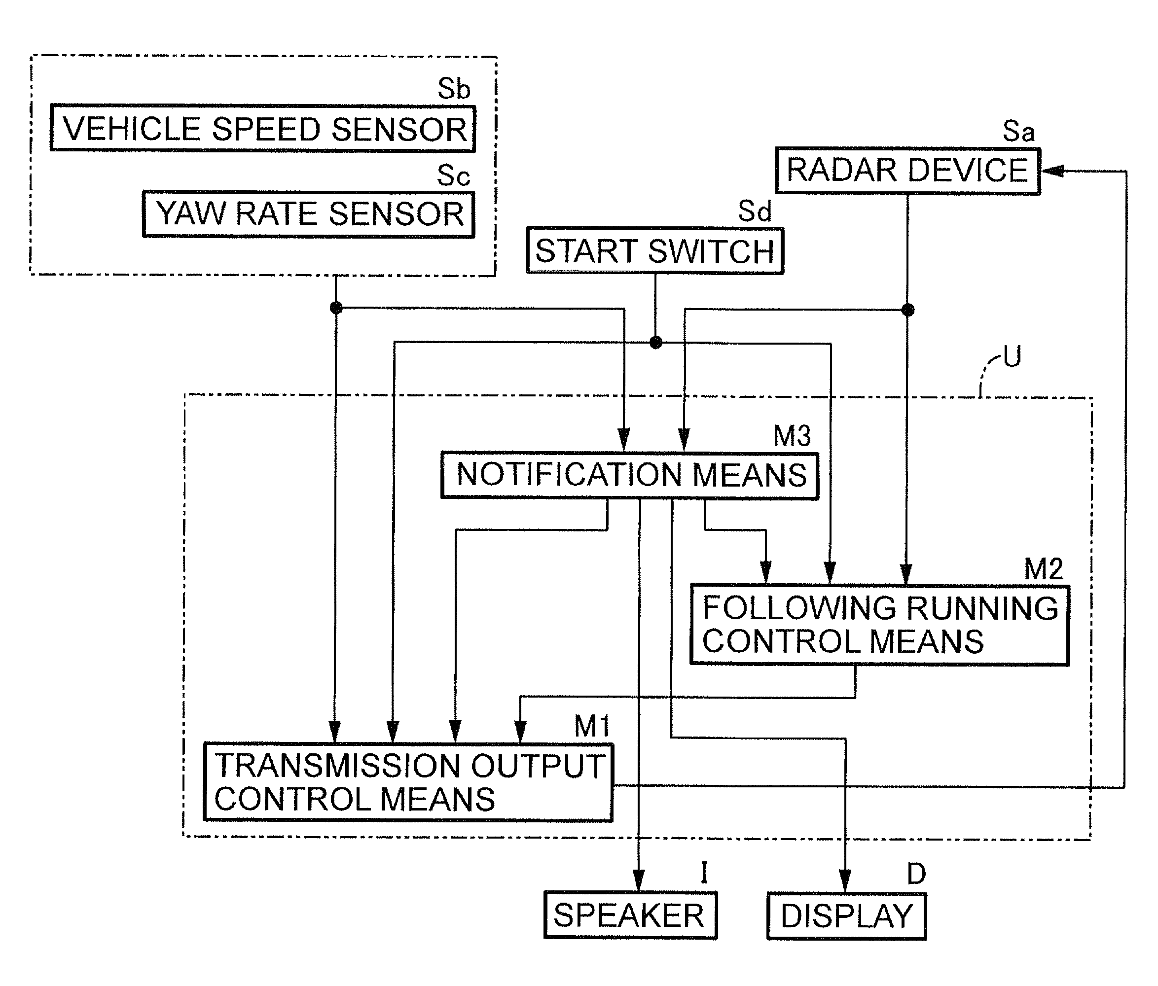
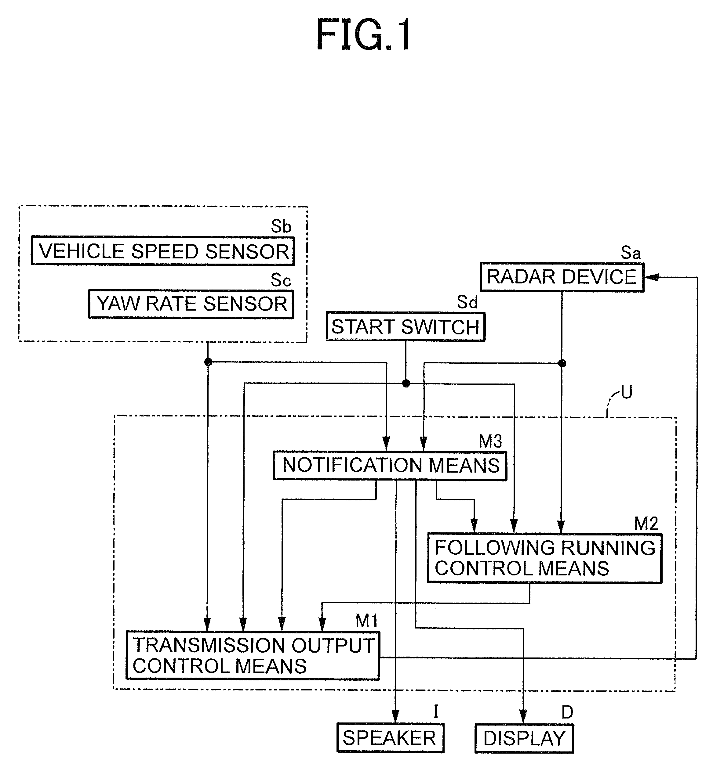
The present invention provides a reliable following running control system for a vehicle that can control its speed and distance from a preceding vehicle, even when the radar device detects a reduction in its output due to stoppage of the vehicle. The system includes a radar device that detects the distance between the vehicle and the preceding vehicle, a vehicle speed sensor that detects the vehicle's speed, and a transmission output control means that adjusts the radar device's output based on the vehicle's speed and the distance between the vehicle and the preceding vehicle. The system also includes notification means that notify the occupant of the vehicle that the following running control is possible, and a detection means that detects the occupant's command operation to start the following running control. The system ensures that the vehicle can control its speed and distance from the preceding vehicle, even when the radar device detects a reduction in its output.

Problems solved by technology

Also, even without the legal regulations of such countries being a concern, cooling of a radar device with running air cannot be accomplished while the vehicle is stopped.
Thus, the radar device may overheat and have a reduced durability while the vehicle is stopped unless a transmission output of the laser beam is reduced to be lower than when operating during a normal state.
However, for a vehicle having a congestion following system which starts and stops the subject vehicle according to the starting and stopping of a preceding vehicle in heavy traffic, if a transmission output of a radar device is reduced during stoppage of the subject vehicle, the radar device with the reduced transmission output is prone to lose sight of the preceding vehicle when a stopped preceding vehicle starts moving again and increases a distance between the subject vehicle and the preceding vehicle, which makes smooth following running control of the subject vehicle toward the preceding vehicle difficult.

Method used


Image

  • Running control system for vehicle
  • Running control system for vehicle
  • Running control system for vehicle

Examples


second embodiment

[0053]FIGS. 6 to 9 show the present invention.

[0054]The first embodiment can be applied when the transmission output of the radar device Sa is set to the power-up mode during stoppage of the subject vehicle under legal regulations, but cannot be applied when it is mandatory to set the transmission output of the radar device Sa to the power-down mode during stoppage of the subject vehicle. The second embodiment is a measure for the case where it is mandatory to set the transmission output of the radar device Sa to the power-down mode during stoppage of the subject vehicle.

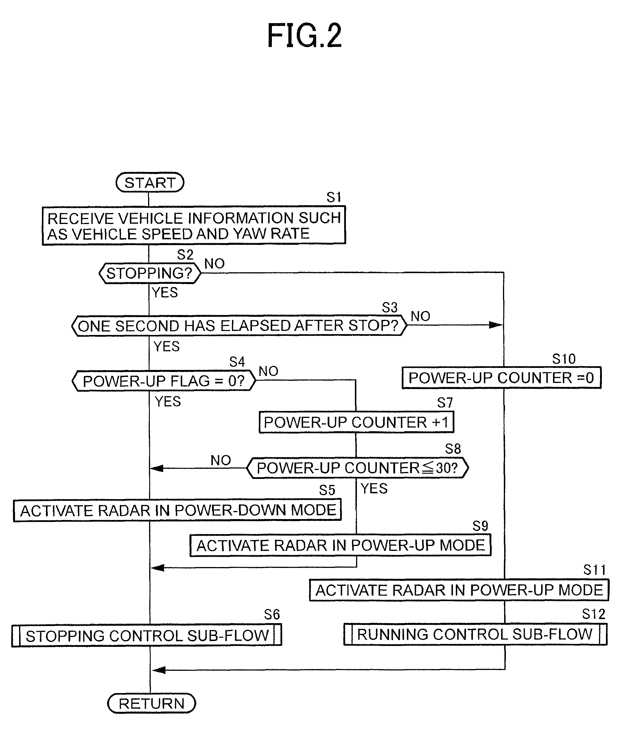
[0055]First, in Step S51 of FIG. 6, the vehicle speed sensor Sb and the yaw rate sensor Sc detect the vehicle speed and the yaw rate of the subject vehicle. When both the vehicle speed and the yaw rate are equal to or less than a predetermined threshold or value, and it is determined that the subject vehicle is stopping in Step S52, and one second has elapsed after the stop in Step S53, the radar device Sa is activa...


PUM


Abstract

A running control system having a radar device that detects a distance between a subject vehicle and a preceding vehicle. When a vehicle speed sensor detects the subject vehicle has stopped, a transmission output controller sets a transmission output of the radar device to a stopping time transmission output lower than a running time transmission output. When the radar device detects an increase in the distance between the subject vehicle and the preceding vehicle while the subject vehicle is stopped, or when the distance between the subject vehicle and the preceding vehicle detected by the radar device while the subject vehicle has stopped is longer than a predetermined value, a notifying device notifies an occupant of the subject vehicle that following running control is possible.

Description

CROSS-REFERENCE TO RELATED APPLICATIONS[0001]This application is based upon and claims the benefit of priority from the prior Japanese Patent Application No. 2007-305475, filed Nov. 27, 2007, the entire contents of which is incorporated herein by reference.BACKGROUND OF THE INVENTION[0002]1. Field of the Invention[0003]The present invention relates to a running control system for a vehicle.[0004]2. Description of the Related Art[0005]Radar devices that use a laser beam as a detection medium may affect eyesight of pedestrians or the like if the laser beam is applied to their eyes for a predetermined time or more. For this reason, a device that reduces a transmission output of a laser beam while a vehicle is stopped is disclosed in Japanese Patent No. 3261345.[0006]In some countries, it is mandatory to reduce a transmission output of a laser beam while a vehicle has stopped. Also, even without the legal regulations of such countries being a concern, cooling of a radar device with runn...

Claims


Application Information

Patent Timeline
Patent Type & Authority Patents(United States)
IPC IPC(8): G01S13/00G01S17/931B60K31/00B60W30/16
CPCB60W30/17G01S17/936G01S7/484G01S17/931
Inventor KIKUCHI, HAYATO
Owner HONDA MOTOR CO LTD
Learn More