Magnetic fabric retaining device

a magnetic fabric and retaining device technology, applied in the field of embroideries and monogramming, can solve the problems of difficult and time-consuming, improper embroidering of items such as items, and difficulty in using standard embroidery hoops, and achieve the effect of convenient application to garments

Active Publication Date: 2011-06-28
MIDWEST PRODS
View PDF32 Cites 15 Cited by
  • Summary
  • Abstract
  • Description
  • Claims
  • Application Information

AI Technical Summary

Benefits of technology

[0012]The present invention provides a hoop used with embroidery machines that is easy to apply to garments and align during the hooping process. The device generally comprises upper and lower clamping members, with the clamping members being secured to one another by use of a magnetic force, preferably with rare earth magnets. The magnets provide a solid, secure mating arrangement between the upper and lower clamping members.
[0014]The lower clamping member may also be a shape that would align itself with a hoop holding bracket or device on a hooping board to assist in proper alignment of the hoop with an item to be embroidered. Alignment could also be accomplished in other manners, such as a pin in the hoop holding bracket and a corresponding hole in the lower hoop member, or the opposite arrangement. The lower clamping member could also have pins or another locating means in it to hold it directly to a hooping board without the need for any additional bracket. This is to make it easier to help properly align the clamping members with a piece of material or garment to be embroidered. There could also be a non-slip material like rubber or sandpaper adhered to one or both of the mating surfaces to help hold the article to be embroidered.
[0015]The hoop may have a compressible material attached to the underside of the upper member to assist in gripping the material that is placed between the clamping members. This compressible material also helps when embroidering items with seams and other uneven surfaces.
[0017]The hoop of the present invention does not need a biasing spring by the hinge or pivot point so the sewing area is not reduced. As the strength of the selected magnet or magnets is sufficiently strong, the hoop is effective at holding various types and thicknesses of garments. By comparison, a hoop utilizing springs near the hinge or pivot point may not be sufficiently strong enough to retain a thick or heavy garment. In addition, the material from which the hoop is made must be rigid enough in combination with the spring to hold the hoop in a closed position. Conversely, the hoop of the present invention can be made from lightweight materials since the magnets are holding the upper and lower members together and are ideally farther from the hinge or pivot point.

Problems solved by technology

Because of this, the lower hoop member needs to be adjusted for any change in thickness of the item to be hooped, which may not always result in the material being sufficiently taut or tight, potentially resulting in an improperly embroidered piece of material.
The use of standard embroidery hoops becomes more difficult when the item to be embroidered is a heavier or thicker material, such as a winter jacket, work overalls, Carhartt® type jackets, or items made of leather.
Properly embroidering such items can be very difficult and time consuming.
It is very difficult to figure out what adjustment should be made to the lower hoop or clamping member to securely hold the garment, while not having too tight of an arrangement that the two clamping members cannot properly mate with one another.
It often takes multiple tries to get the adjustment correct.
These clamping members are spring loaded to allow for different thickness of material to be held without adjustment, but they do have limitations.
Because of the need for a pivot point and at least one spring for biasing the base plate and upper clamping member in closed contact, the maximum sewing area of the embroidery machine is further limited by this prior art space requirement.
Such rigid material, and the extra mechanism needed for the pivot point and spring bias, makes the clamps heavier than standard hoops, with the added weight applying unnecessary stress to the mechanical and electrical components of the embroidery machine.
The physical size of the clamp can also cause damage to some embroidery machines if the entire body of the clamp cannot fit under the needle bars used for embroidery.
This type of frame is very good for getting into small areas like pockets on garments, or for sewing on delicate fabrics, but is not really designed for everyday normal hooping of garments; it is more for specialty items.
One disadvantage to these frames is the need for special sticky backing, which is generally more expensive than standard backing and can leave a residue on the needles of the embroidery machine over time.
The residue can cause increased thread breaks and other problems.
Also, the backing material has a limited number of uses before it needs to be removed from the frame and a new piece applied, which can increase the production time needed to complete a job.
The sticky backing is not strong enough to adequately hold heavy items like Carhartt® type jackets during the embroidery process.
The extra expense and increase in production time that is created by the use of sticky backing makes the sticky backing type of frame impractical for most normal placements of designs on shirts and jackets.
The hoop from this prior art device is not designed to be releasably mounted to the existing hoop holding arms on these newer style commercial embroidery machines.
This outdated design increases the time it takes to switch from using one type of frame to another.
This prior art frame does not incorporate a special compressible material to allow it to hoop uneven or thick items.
This prior art frame also does not allow for the controlling of when the upper and lower members will be attracted to each other.

Method used


Image

  • Magnetic fabric retaining device
  • Magnetic fabric retaining device
  • Magnetic fabric retaining device

Examples


Embodiment Construction

[0029]Although the disclosure hereof is detailed and exact to enable those skilled in the art to practice the invention, the physical embodiments herein disclosed merely exemplify the invention which may be embodied in other specific structures. While the preferred embodiment has been described, the details may be changed without departing from the invention, which is defined by the claims.

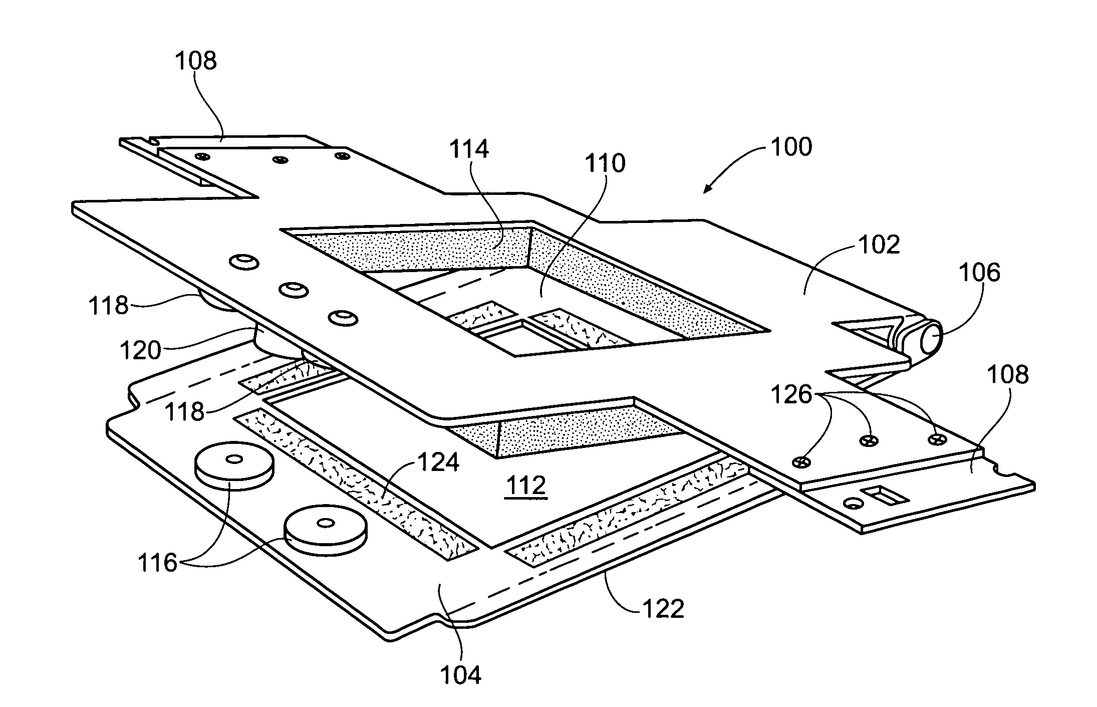
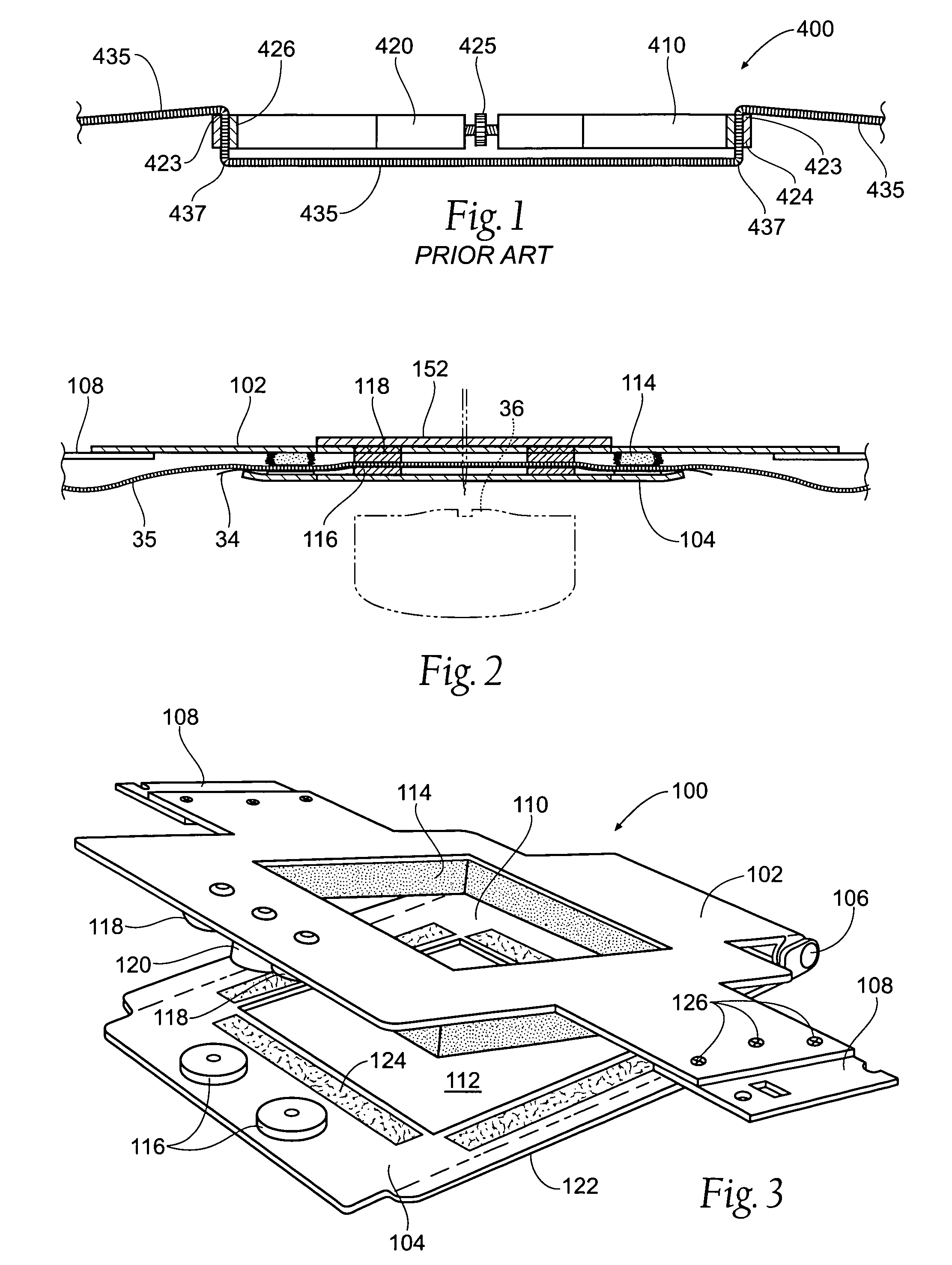
[0030]The present invention provides a hoop used with embroidery machines that is easy to apply to garments of varying thickness and align during the hooping process. Likewise, alignment can be accomplished quickly and efficiently, regardless of the thickness of the material being placed within the hoop, without distorting the area that embroidery is being placed upon. FIGS. 1 and 2 compare differences in securing material according to the prior art with the present invention. FIG. 1 demonstrates the prior art, while FIG. 2 provides an arrangement according to the present invention.

[0031]FIG. 1 sh...


PUM


Abstract

A device for use with an embroidery machine to hold an item or material to be embroidered between upper and lower hooping members, with the hooping members being secured to one another by use of a magnetic force, preferably with rare earth magnets, is disclosed. The magnets provide a solid, secure mating arrangement between the upper and lower hooping members without the need to adjust for different thicknesses of material. Compressible and / or frictional material may be attached to at least one hooping member to securely retain the item or material to be embroidered. One hooping member has interchangeable arms for attaching the mating hooping members to different brands of embroidery machines. One hooping member may also include a locating device for attaching the hooping members to a hooping device such as a hooping board.

Description

RELATED APPLICATIONS[0001]This is a continuation-in-part patent application of U.S. patent application Ser. No. 12 / 072,775, filed on 28 Feb. 2008, now U.S. Pat. No. 7,607,399 which claims the benefit of U.S. Provisional Patent Application Ser. No. 60 / 903,997, filed on 28 Feb. 2007.BACKGROUND OF THE INVENTION[0002]The present invention relates to the field of embroidery and monogramming and more specifically to a hoop that incorporates magnets to hold and secure a garment, piece of material, or other item to be embroidered.[0003]In the embroidery industry “hoop” or “hoops” are referred to by many different terms, like frame, clamp, hooping device, fabric holding device, fabric retaining device and fabric mounting frame. The definition of each of these terms is intended to apply to all of these terms to give these terms their broadest meaning individually and collectively as they are used interchangeably herein. In an instance where the term or terms have more than one meaning, all me...

Claims


Application Information

Patent Timeline
Patent Type & Authority Patents(United States)
IPC IPC(8): D05C9/04D05B39/00
CPCD05C9/04
Inventor MACK, CHARLES H.MACK, JESSE C.
Owner MIDWEST PRODS
Why Eureka
Try Eureka