Recreational vehicle with elliptical drive

a technology of elliptical drive and recreational vehicles, which is applied in the direction of foot-driven levers, transportation and packaging, cycles, etc., can solve the problems of riders having difficulty maintaining the balance of the vehicle, discomfort and fatigue, and limited exercise components, so as to achieve natural feel, reduce the risk of tipping, and the effect of smooth operation

Inactive Publication Date: 2011-06-28
EGGERT WILLIAM E
View PDF23 Cites 37 Cited by
  • Summary
  • Abstract
  • Description
  • Claims
  • Application Information

AI Technical Summary

Benefits of technology

[0022]The controllers and handle regions are positioned and oriented to provide several advantages. One of these is more efficient usage of the push / pull forces exerted through the shoulders and arms of the rider, particularly when the upper end regions of the thrust levers are substantially linear and vertical. With each controller axis located within its associated plane of thrust lever travel, and each handle region centered on its associated axis, the push / pull forces are exerted directly through each upper end region. There is no transverse offset, and accordingly no rotational moment or torque applied to the upper end region. As compared to conventional systems with transversely offset control handles, the present controllers more directly apply and thus more efficiently use the motive force exerted by the operator. In addition, undesirable rotational moments and torque are minimized, increasing the useful life of the thrust levers.
[0033]Thus in accordance with the present invention, vehicles powered at least in part through hand operated levers are steerable through more natural, ergonomically preferred motions with minimal risk of tipping. There is a more natural feel, even when the thrust levers are reciprocated during steering. A smoother operation of leg powered drivers is achieved through an indirect coupling of the drivers and hand powered thrust levers. Finally, an auxiliary steering system allows the user to power a manually operated vehicle through the lower body and rest the upper body, while maintaining steering control.

Problems solved by technology

The exercise component is somewhat limited, however, in the sense that vigorous activity is concentrated along the lower body as the legs and feet move the pedals in circular paths to propel the drive sprocket.
Another concern is the seated position of the rider, which can be a source of discomfort and fatigue over extended periods of use.
Riders may have difficulty maintaining the balance of the vehicle, given how the steering handles differ from a typical bicycle handlebar.
This positions the backs of the hands to face upward, which is ergonomically undesirable.
The steering method appears to be ergonomically difficult in that the rider must turn the front wheel by rotating a cross bar with the arm levers while reciprocating the arm levers fore and aft.
One problem with this method is that while the rider applies a leftward force vector to pivot the upper ends of the arm levers, the upper body tends to counteract the force by leaning to the right.
This increases the tendency to tip.
Another problem with the Krul and Heath steering approach is that the pivotable upper ends of the arm levers are spaced apart from the planes in which the arm levers reciprocate.
This spacing or misalignment varies as the upper ends are pivoted, and causes the hands and arms, when reciprocating the arm levers to propel the vehicle, to also apply an undesirable torque or rotational force to the arm levers.
The result is an unwanted twisting along the arm levers, reducing efficiency and generating stress concentrations that can lead to metal fatigue and plastic deformation or fracture.
While the vehicles taught by Kraus, Krul, Heath and Keay may usefully combine upper body and lower body exercise, none of them accommodates the tendency of the shoulders and arms to become fatigued earlier than the legs and feet during extended operation of the vehicle.

Method used


Image

  • Recreational vehicle with elliptical drive
  • Recreational vehicle with elliptical drive
  • Recreational vehicle with elliptical drive

Examples


Embodiment Construction

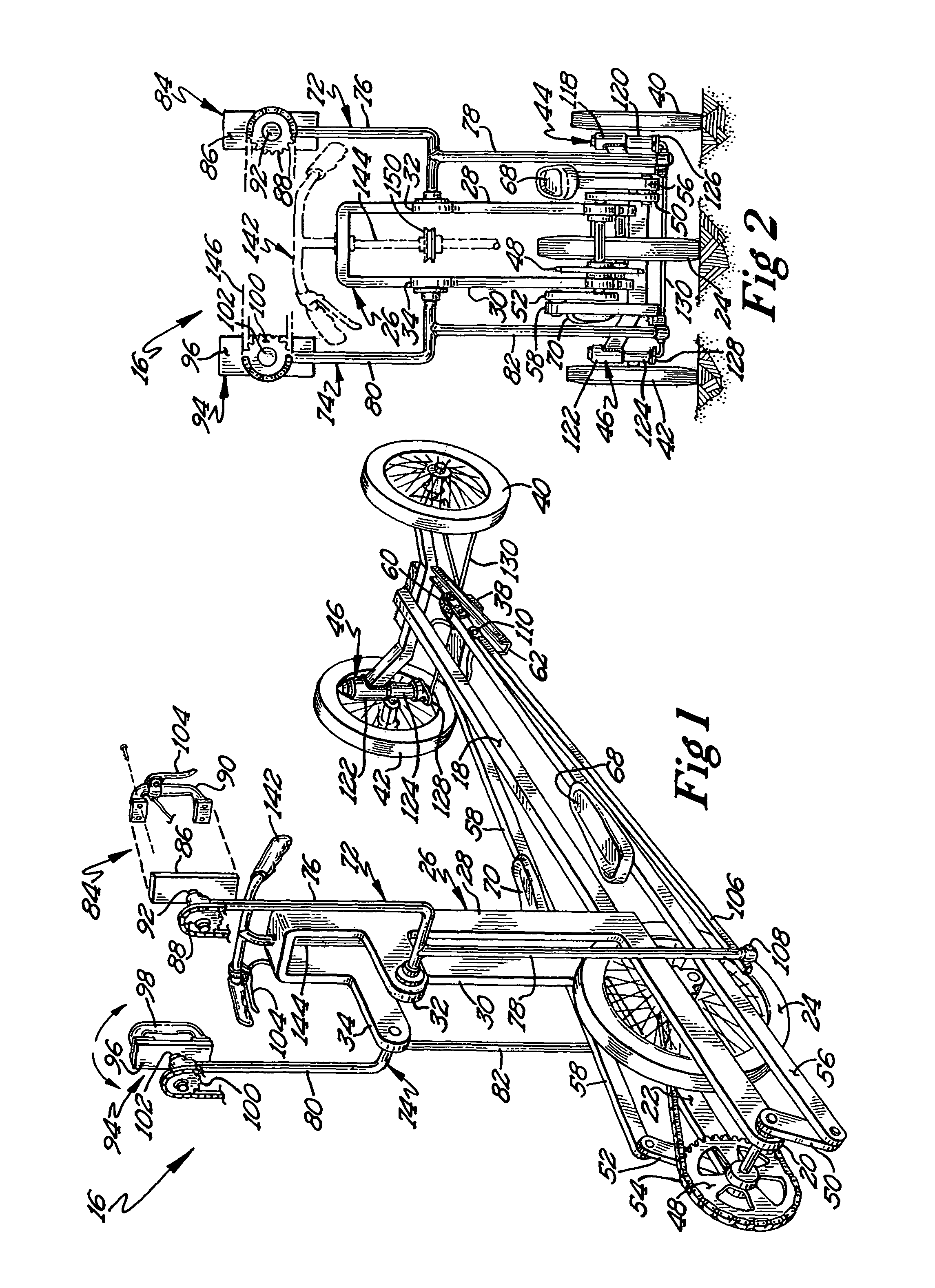
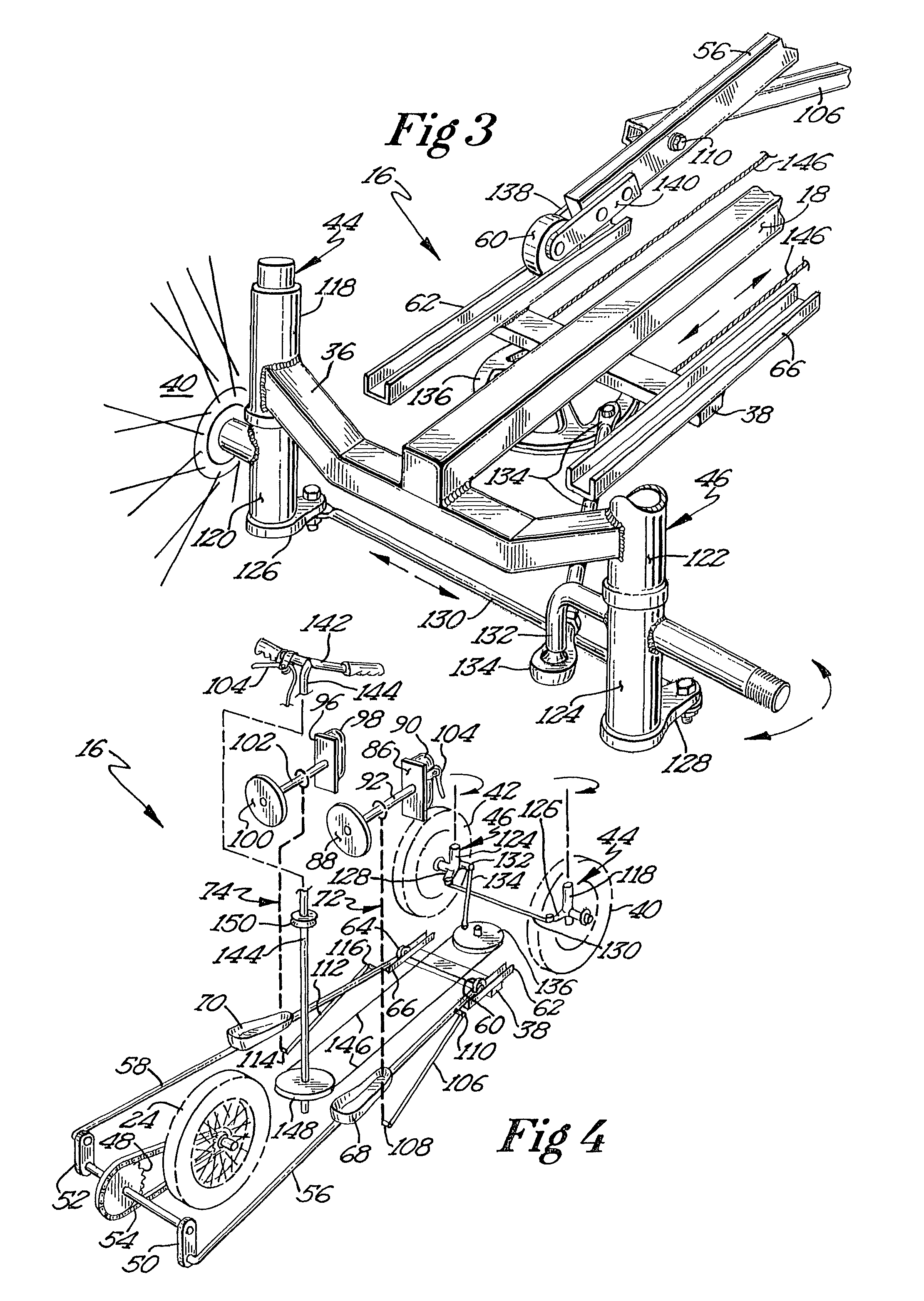
[0042]Turning now to the drawings, there is shown in FIGS. 1-3 a manually powered wheeled vehicle 16 constructed in accordance with the present invention. Vehicle 16 has a substantially rigid structural frame including an elongate longitudinal frame member 18. Longitudinal forward frame sections 20 and 22 extend forwardly from opposite sides of frame member 18, forming a fork to accommodate a front wheel 24.

[0043]The frame further includes an upright column 26 having left and right upright column sections 28 and 30 on opposite sides of longitudinal frame member 18. Lever support sections 32 and 34 extend forwardly from upright sections 28 and 30, respectively.

[0044]A steering wheel mounting structure 36 is fixed to a rearward region of frame member 18 and extends generally transversely away from the frame member in opposite directions. A transverse support or cross member 38 is fixed to frame member 18 at a location slightly ahead of mounting structure 36.

[0045]Rear wheels 40 and 42...


PUM


Abstract

A wheeled vehicle includes a pair of leg driven skis and hand operated levers for simultaneously applying power to a crank and drive sprocket to propel the vehicle. A pair of controllers, one at the top of each thrust lever, include handles that are pushed and pulled to reciprocate the levers and may simultaneously be rotated through wrist and forearm action to steer the vehicle. Auxiliary steering is provided through a handlebar mounted to the vehicle separately from the thrust levers. The skis are operatively coupled to their associated levers, either directly through a pivotal connection or indirectly through an elongate link rotatably coupled at one end to the lever and at the other end to the ski.

Description

[0001]This application claims the benefit of priority based on Provisional Application No. 60 / 969,240 entitled “Recreational Vehicle with Elliptical Drive,” filed Aug. 31, 2007.BACKGROUND OF THE INVENTION[0002]The present invention relates to manually powered wheeled vehicles, and more particularly to vehicles equipped to provide a higher level of upper body exercise as compared to conventional bicycles.[0003]For many years, bicycles and other wheeled vehicles on the order of bicycles (e.g. tricycles) have provided recreation, exercise, and enjoyment as well as a useful means of transportation for individuals and their property. The exercise component is somewhat limited, however, in the sense that vigorous activity is concentrated along the lower body as the legs and feet move the pedals in circular paths to propel the drive sprocket. Another concern is the seated position of the rider, which can be a source of discomfort and fatigue over extended periods of use.[0004]To address th...

Claims


Application Information

Patent Timeline
Patent Type & Authority Patents(United States)
IPC IPC(8): B62M1/00
CPCB62K5/02B62M1/26B62M1/12
Inventor EGGERT, WILLIAM E.
Owner EGGERT WILLIAM E
Why Eureka
Try Eureka