Vacuum thermal insulation with inflatable load-carrying structure

a technology of vacuum insulation and load-carrying structure, which is applied in the direction of insulation improvement, packaging goods, paper/cardboard containers, etc., can solve the problem that the atmospheric pressure tends to scrunch the vacuum container

Inactive Publication Date: 2011-06-28
YEGANEH MEHDI
View PDF2 Cites 6 Cited by
  • Summary
  • Abstract
  • Description
  • Claims
  • Application Information

AI Technical Summary

Benefits of technology

[0030]Insulation with inflatable load-carrying structure according to the present invention can be used not only for flat shapes such as elliptical, square and orthogonal, but also for insulation with cylindrical, spherical or any other three dimensional shapes. In such cases the structure should be designed in a manner that could recover the desired shape after inflation. The ability to be manufactured in different forms and shapes including multi-layer or curved insulation is an advantage of the present invention. Another advantage of the present invention is the provision of an inflatable vacuum insulation which has small volume in non-operational condition. This insulation can be temporarily deflated by removing high pressure air from its structure to reduce the volume of the insulation. The reduction in volume significantly increases the convenience and reduces the expense of transportation of the insulation. At its destination, by entering high pressure air into the structure, the insulation could be inflated to its operational shape. One of advantages of the proposed vacuum insulation is the ability of draining the air inside the vacuum chamber trough the vacuum gate. Yet another advantage of the present invention is the provision of an inflatable vacuum insulation which has low weight with respect to other types of vacuum insulations and could be produced in inexpensive and convenient manufacturing process. Needless to filling material for carrying the load of atmospheric pressure is another important advantage of this invention, which significantly reduces the cost of row materials. However, the thermal conductivity coefficient of the proposed insulation is low, if it needs there is the ability to increase the thermal conductivity coefficient by changing the distance between outer surfaces of the insulation by decreasing the inside air pressure. Having the ability of no limited deflation and inflation, the proposed insulation is proper for cases of periodical usage with short time of application.
. Another advantage of the present invention is the provision of an inflatable vacuum insulation which has small volume in non-operational condition. This insulation can be temporarily deflated by removing high pressure air from its structure to reduce the volume of the insulation. The reduction in volume significantly increases the convenience and reduces the expense of transportation of the insulation. At its destination, by entering high pressure air into the structure, the insulation could be inflated to its operational shape. One of advantages of the proposed vacuum insulation is the ability of draining the air inside the vacuum chamber trough the vacuum gate. Yet another advantage of the present invention is the provision of an inflatable vacuum insulation which has low weight with respect to other types of vacuum insulations and could be produced in inexpensive and convenient manufacturing process. Needless to filling material for carrying the load of atmospheric pressure is another important advantage of this invention, which significantly reduces the cost of row materials. However, the thermal conductivity coefficient of the proposed insulation is low, if it needs there is the ability to increase the thermal conductivity coefficient by changing the distance between outer surfaces of the insulation by decreasing the inside air pressure. Having the ability of no limited deflation and inflation, the proposed insulation is proper for cases of periodical usage with short time of application.

Problems solved by technology

Since the inside pressure of vacuum insulation is very low, therefore the atmospheric pressure tends to scrunch the vacuum container.

Method used


Image

  • Vacuum thermal insulation with inflatable load-carrying structure
  • Vacuum thermal insulation with inflatable load-carrying structure
  • Vacuum thermal insulation with inflatable load-carrying structure

Examples


example 1

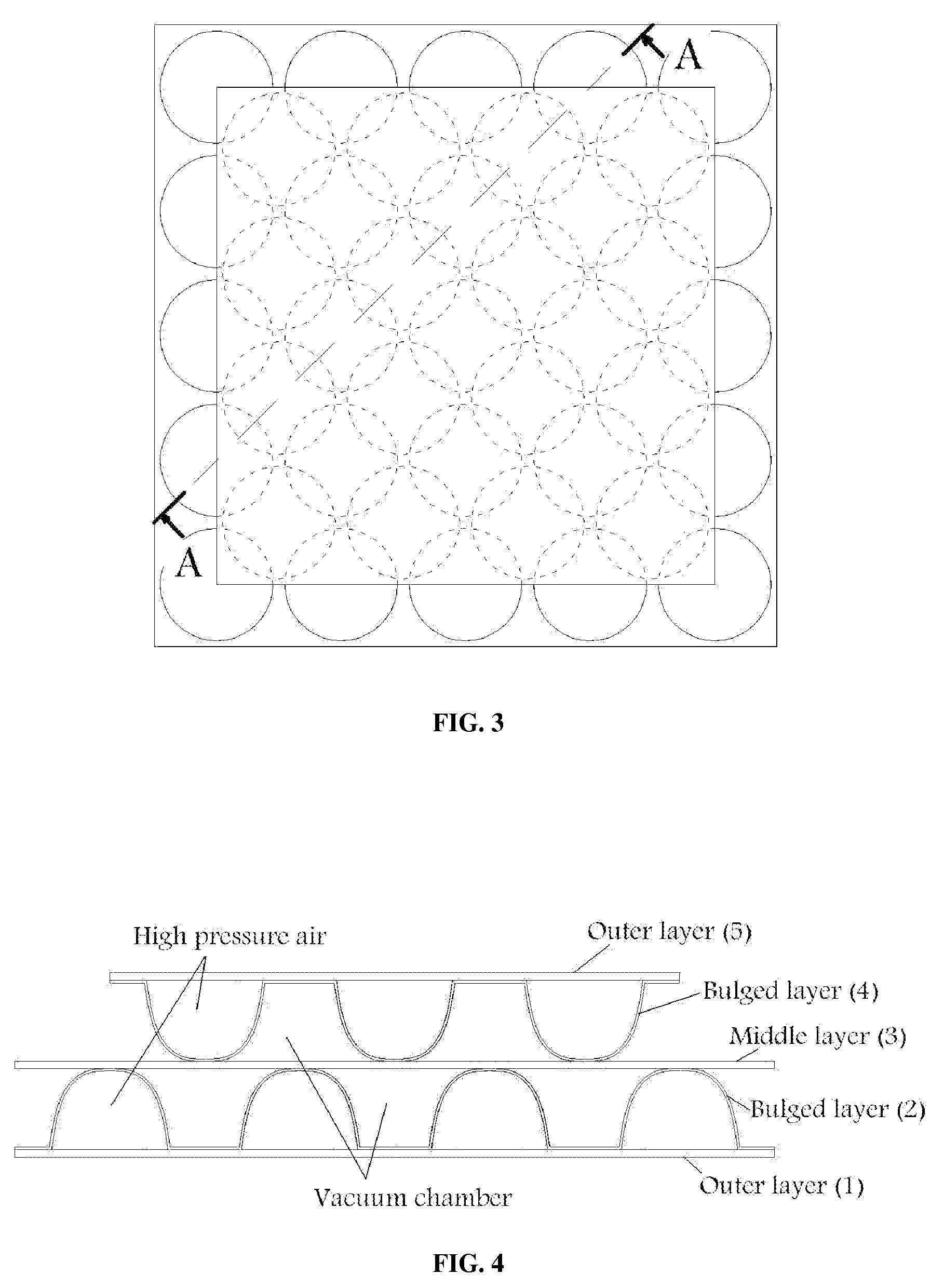
[0031]It is well known that in vacuum insulations the insulating effect will depend upon the extent of the vacuum, as well as the configuration of the remainder of the structure, including the amount of continuous structural contact between the opposing surfaces. Such structural contact will result in heat conduction between the surfaces. The proposed insulation is analyzed to investigate the effect of such parameters on thermal characteristics. Also the state of stress in the structure under the atmospheric and inside pressure loading is studied.

[0032]Structural Analysis

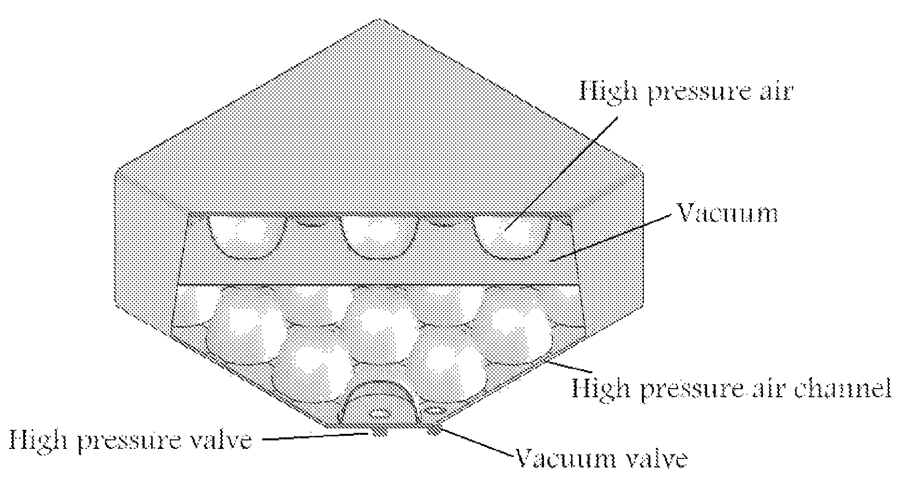
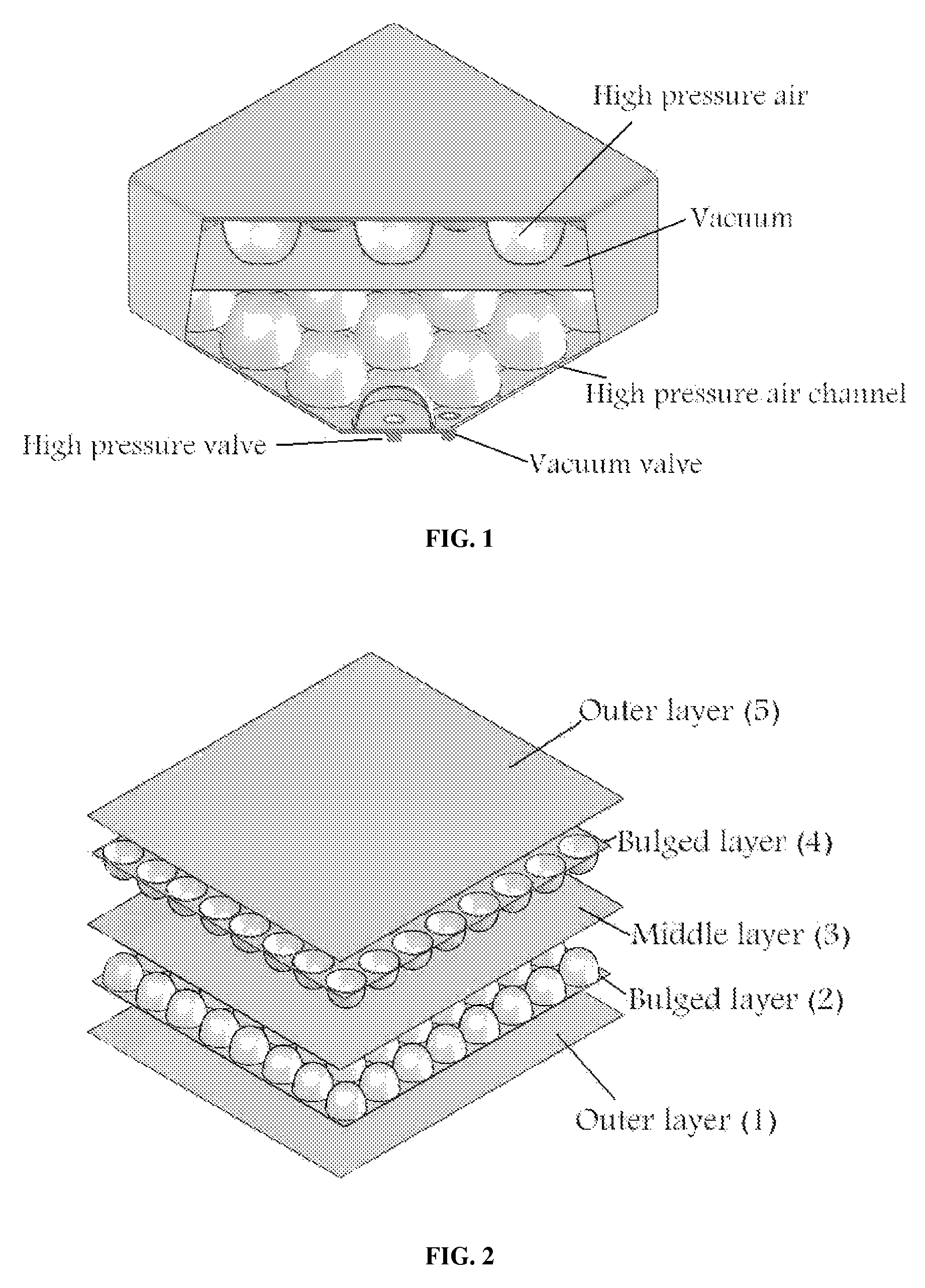
[0033]In the proposed insulation, bulges are main parts of the load-carrying structure. The bulges' area to total area determines the required inside pressure of structure to inflate the insulation. This ratio is the main parameter affecting the thermal efficiency of insulation. In other words the greater inside pressure of structure leads to a smaller required bulge area, which yields to a greater vacuum area and t...


PUM

PropertyMeasurementUnit
pressureaaaaaaaaaa
bulge's radiusaaaaaaaaaa
distanceaaaaaaaaaa

Abstract

A vacuum thermal insulation comprises an inflatable load-carrying structure and gas impermeable envelope with proper gates for inserting pressurized air into the structure and an evacuating vacuum chamber wherein, pressurized air is used for inflating and stiffening the load-carrying structure in order to prevent scrunching the envelope due to the atmospheric pressure. Thereby, producing vacuum in locations which are out of structure.

Description

TECHNICAL FIELD OF THE INVENTION[0001]The present invention relates to vacuum thermal insulation and methods for manufacturing the same.SPONSORSHIP STATEMENT[0002]The present invention is sponsored by Iranian National Science foundation.BACKGROUND OF THE INVENTION[0003]The increasing attention to the environmental issues has led to new regulations to limit energy consumption. These measures as well as the rise continuation of the cost of energy are having significant impact on energy consumers, which have been pushed either to optimize existing technologies or adopt new technical solutions to reduce energy consumption. Modification of insulation methods to reduce heat loss or heat entry is one of these solutions.[0004]It is well known that a vacuum acts as a barrier to heat flow, and hence, certain insulating materials have included a vacuum or partial vacuum to increase their heat insulating effect. Application of vacuum insulations, which have insulation efficiency up to 7 times b...

Claims


Application Information

Patent Timeline
Patent Type & Authority Patents(United States)
IPC IPC(8): B29D22/00B29D22/02F25D11/00
CPCE04B1/803E04B1/806Y02B80/12Y10T428/13Y10T428/23Y10T428/1328Y10T428/231Y02A30/242Y02B80/10
Inventor YEGANEH, MEHDI
Owner YEGANEH MEHDI
Why Eureka
Try Eureka