Open architecture imaging apparatus and coil system for magnetic resonance imaging

a coil system and open architecture technology, applied in the field of magnetic resonance imaging, can solve the problem of not providing for specialized applications required

Active Publication Date: 2011-06-28
INVIVO CORP +1
View PDF76 Cites 63 Cited by
  • Summary
  • Abstract
  • Description
  • Claims
  • Application Information

AI Technical Summary

Benefits of technology

[0019]A desirable element of the present technology is the capability of providing a patient support structure in combination with the coil. In the use of a stable, secure and robust support, the coils may be removed and replaced (e.g., with coils having different field geometries as well as for repair) without disturbing the patient.
[0020]The benefits of a coil system separable from its housing or patient support structure include the ability to 1) configure a combined Field of View (FOV) optimized for the patient anatomy, 2) make use of all available receive channels and concentrate them on imaging only the desired field of view, 3) permit repositioning, replacing or removing coil elements without moving the patient such that openings are created for image-guided interventions, 4) use coil elements intended for higher or lower field strength or different nuclei, 5) deliver separable transmit and receive coil elements having different geometries, 6) provide for coil and compression arrangements that are optimized for positioning tissues (such as the breast) in various arrangements to facilitate and aid in subsequent imaging or surgical procedures, 7) allow different coil configurations to be made available to a physician without the need for separate support structures for each configuration, or 8) upgrade coil elements with new or enhanced functionality without the need to replace the entire assembly.

Problems solved by technology

In no case does the prior art focus on a singular anatomy and related structures and therefore do not provide for specialized applications required for that anatomy and related structures. i.e. have sets of coils adapted to fit different imaging needs with that anatomy, i.e. many sets of breast coils (some for high SNR, some for parallel imaging, some for interventions, some sized to smaller patients, some for spectroscopic applications), and the distinction is not made between a various aspects that make up a coil (the electronics, the coil housing-physical support for the electronics).

Method used


Image

  • Open architecture imaging apparatus and coil system for magnetic resonance imaging
  • Open architecture imaging apparatus and coil system for magnetic resonance imaging
  • Open architecture imaging apparatus and coil system for magnetic resonance imaging

Examples


Embodiment Construction

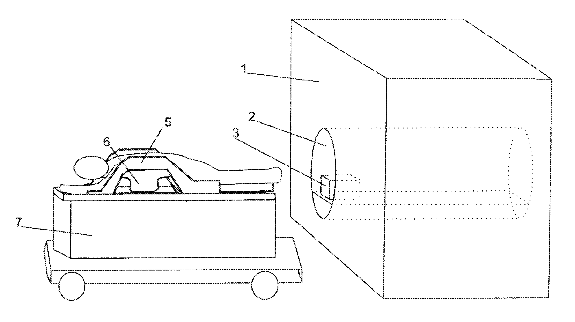
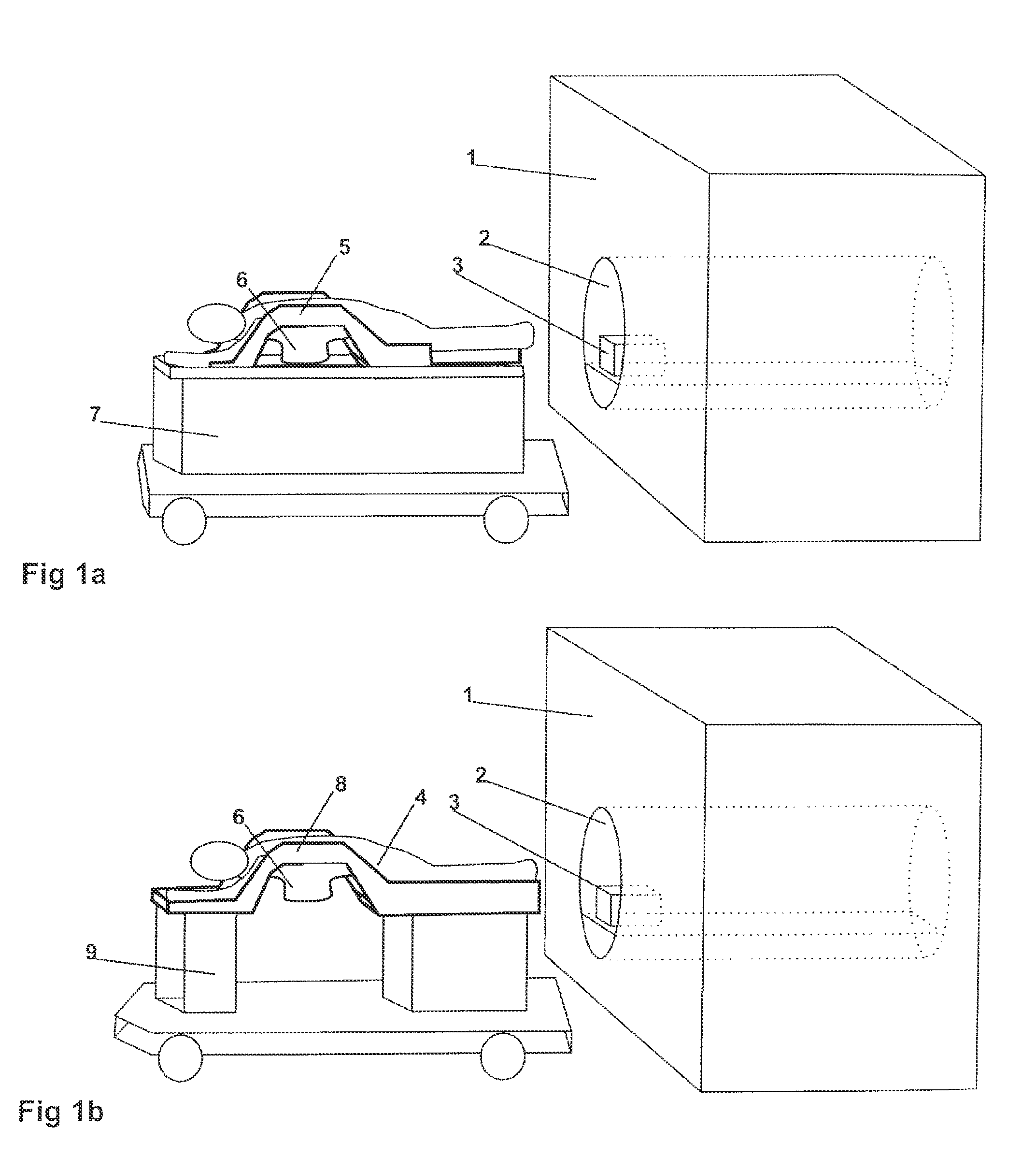
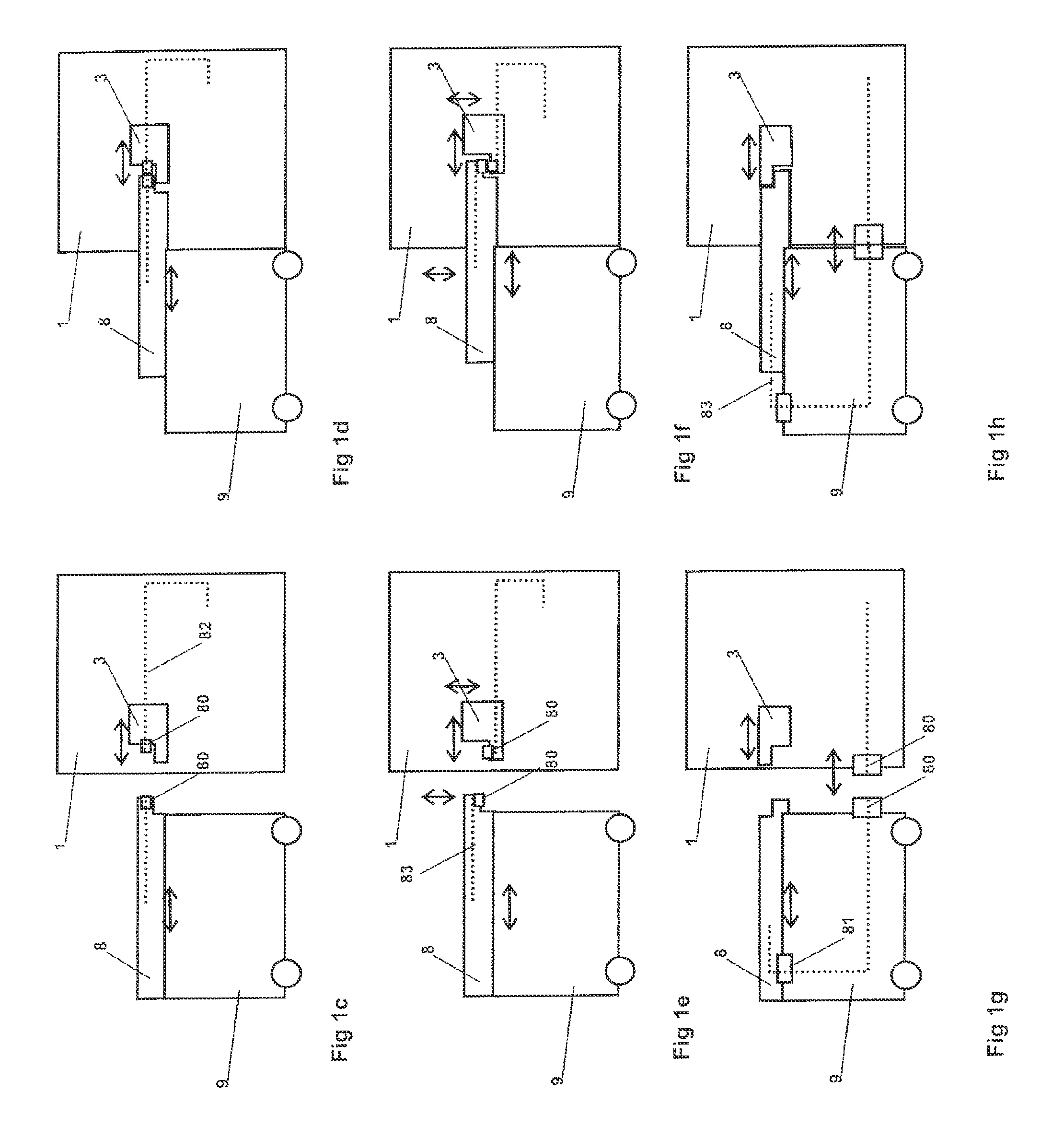
[0036]The following described technology encompasses a method to improve magnetic resonance imaging through use of improved coil systems, associated support structures and apparatus. The preferred embodiments are described by reference to both the general and specific attributes and features of the components of the technology. However, this specification discloses only some specific embodiments as examples of the present technology, which as not intended to be limiting in the interpretation of the scope of the claimed invention of this Patent. It will be readily apparent that numerous variations and modifications may be effected without departing from the true spirit and scope of the novel concepts of the invention.

[0037]This disclosure of technology includes RF coil designs, mechanical system designs and methods of configuring said coils so as to maximize signal arising from said system and enable imaging of anatomy in conformations not previously provided for. In the exemplary ca...


PUM


Abstract

Apparatus and method for using radio frequency coil systems for magnetic resonance imaging within an open architecture apparatus is provided. The MRI coil system includes a support structure with an open architecture in which secondary support structures, compression systems and plates containing RF coil systems may be introduced. These structures and RF coils can be moved relative to the patient, or removed entirely from the system. In one embodiment the system consists of a tabletop coil system, while another embodiment consists of a dedicated stretcher design.

Description

RELATED APPLICATIONS DATA[0001]This application is a continuation-in-part application of U.S. patent application Ser. No. 10 / 916,738, filed Aug. 12, 2004, now U.S. Pat. No. 7,379,769 titled HYBRID IMAGING METHOD TO MONITOR MEDICAL DEVICE DELIVERY AND PATIENT SUPPORT FOR USE IN THE METHOD, which issued as U.S. Pat. No. 7,379,769 on May 27, 2008, which in turn claims priority from U.S. Provisional Application No. 60 / 506,784, filed Sep. 30, 2003.BACKGROUND OF THE INVENTION[0002]1. Field of the Invention[0003]The present invention relates to magnetic resonance imaging (MRI), in particular to an open architecture patient support system with embedded and separable radiofrequency coils and their method of positioning for the use in magnetic resonance imaging and spectroscopy.[0004]2. Background of the Art[0005]Magnetic resonance imaging (MRI) detects the faint nuclear magnetic resonance (NMR) signals given off by protons in the presence of a strong magnetic field after excitation by a radi...

Claims


Application Information

Patent Timeline
Patent Type & Authority Patents(United States)
IPC IPC(8): A61B5/05A47B13/00A61B5/055A61B8/08A61B17/34A61B19/00G01S7/52
CPCA61B5/415G01R33/3678A61B5/4312A61B8/0825A61B8/0841A61B8/406A61B8/5238A61B19/201A61B19/203G01R33/3415A61B5/418A61B2017/3411A61B2017/3413A61B2019/205A61B2019/5236G01R33/34084A61B5/0035A61B90/17A61B90/11A61B90/14A61B2090/374A61B2562/17
Inventor PIRON, CAMERON ANTHONYLUGINBUHL, CHRISTOPHER ALEXANDERPLEWES, DONALD B.
Owner INVIVO CORP
Why Eureka
Try Eureka