Hand drying apparatus

a technology of hand drying and hand, which is applied in the direction of liquid dispensing, special dispensing means, volume measurement, etc., can solve the problems of increasing the cost of the main unit, increasing the pressure loss in the air duct, etc., and achieves the effect of narrow hand detection range, convenient use and high accuracy

Inactive Publication Date: 2011-07-05
MITSUBISHI ELECTRIC CORP
View PDF457 Cites 56 Cited by
  • Summary
  • Abstract
  • Description
  • Claims
  • Application Information

AI Technical Summary

Benefits of technology

[0011]According to the present invention, since the infrared light absorber whose infrared light reflectivity is smaller than that of hands and that absorbs infrared lights is formed on the wall face opposed to the infrared light emitter in the dry space forming unit, infrared lights emitted from the infrared light emitter are substantially absorbed in the infrared absorber, so that improper operations due to diffuse reflection of infrared lights when a person other than a user of the hand drying apparatus approaches to the main unit can be prevented with a high accuracy. Since it is unnecessary to make the hand detection range narrow, which is different from the conventional technique, the hand drying apparatus according to the present invention can be used comfortably without stopping the operation thereof during its use.

Problems solved by technology

In the detecting system of the transmission type, however, since the infrared light emitter and the infrared light receiver are arranged at different positions, the structure of a main unit of the detecting system is complicated, which causes such a problem as increase in pressure loss in an air duct, or increase in cost of the main unit.

Method used


Image

  • Hand drying apparatus
  • Hand drying apparatus
  • Hand drying apparatus

Examples


first embodiment

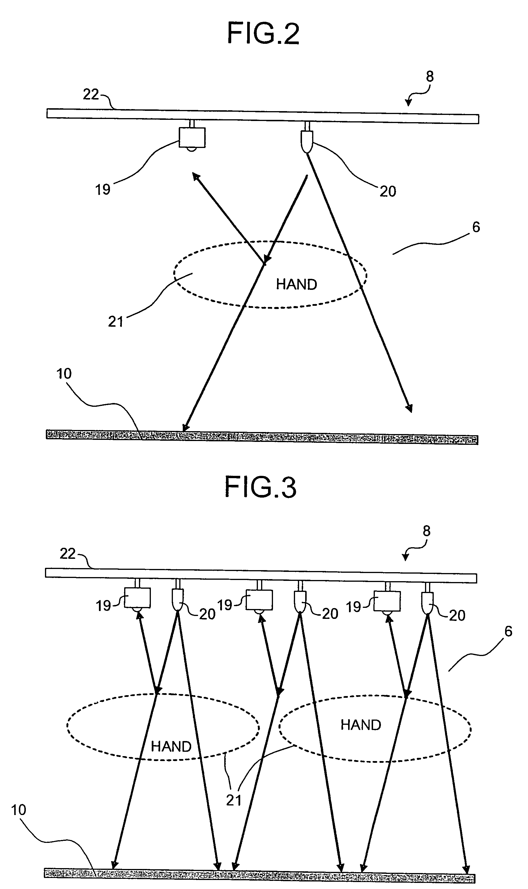
[0037]A hand drying apparatus according to a first embodiment of the present invention will be explained with reference to FIG. 1 to FIG. 3. FIG. 1 is a right side cross-section of a hand drying apparatus according to the first embodiment. FIGS. 2 and 3 are plan views of parts of a hand detector.

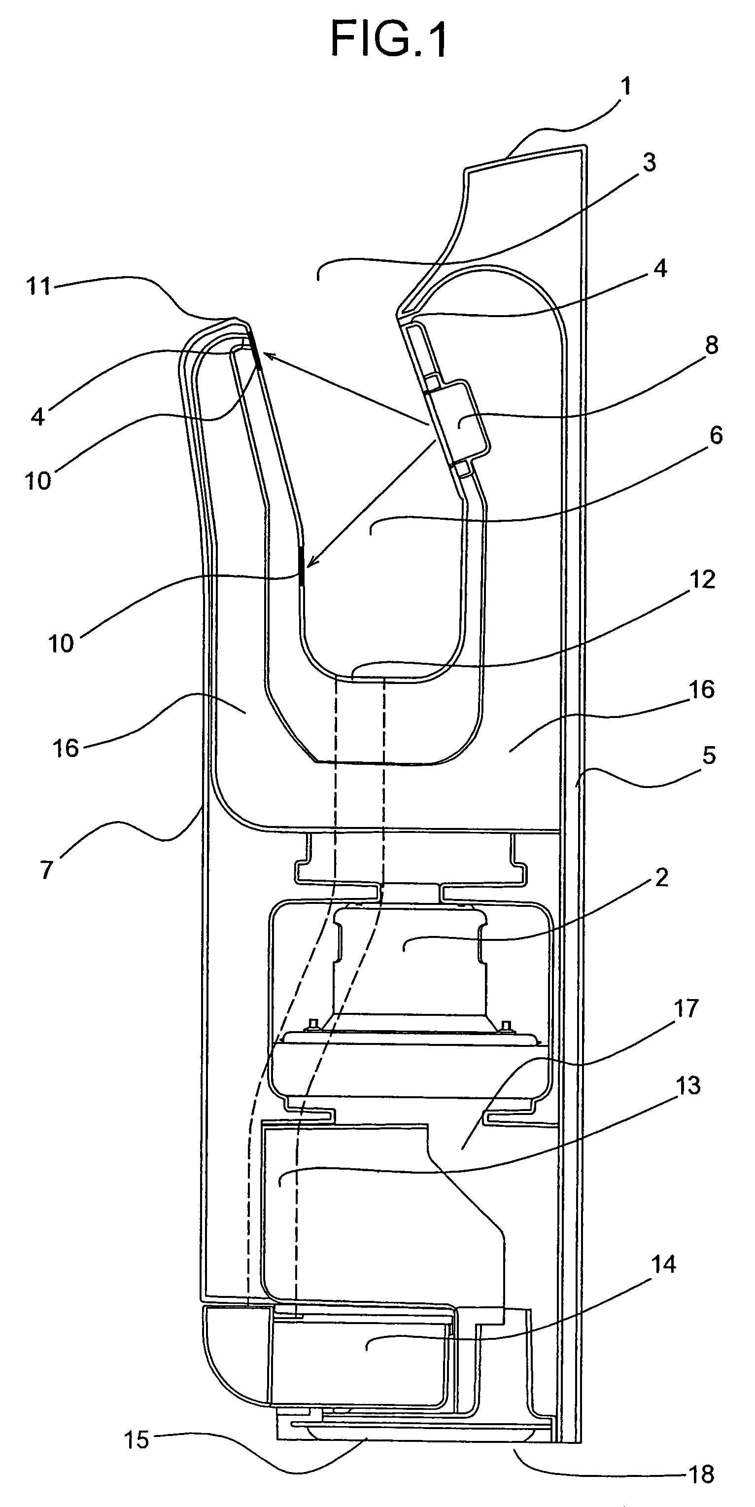
[0038]As shown in FIG. 1, the hand drying apparatus has a main unit box member 1 constituted of a base 5 forming a rear face outer shell and a front panel 7 forming a front face outer shell. A recessed space serving as a hand insertion portion 3 and a drying space 6 is formed on an upper side of the main unit box member 1. The recessed space is formed in an open sink shape with both sides opened and hands can be inserted.

[0039]A high pressure airflow generator 2 is assembled in the main unit box member 1, and a high pressure airflow generated by the high pressure airflow generator 2 is guided to air nozzles 4 provided on a front side wall face and a rear side wall face around the hand insert...

second embodiment

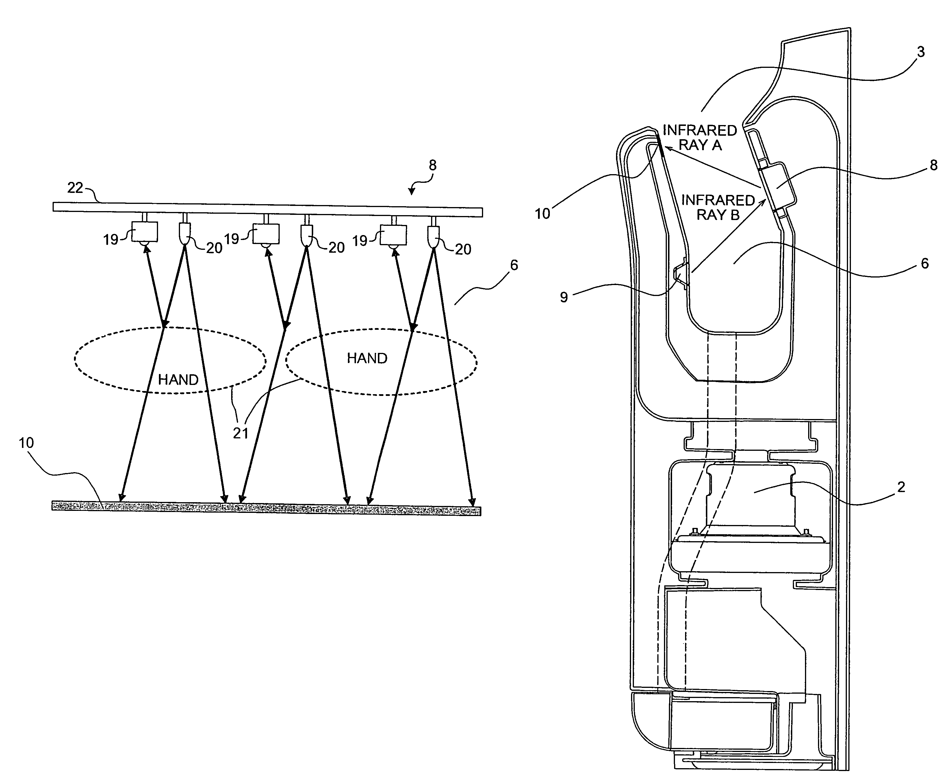
[0055]A hand drying apparatus of a second embodiment of the present invention will be explained next with reference to FIG. 5. In the second embodiment, the hand detector 8 constituted of the infrared light emitter 20 and the infrared light receiver 19 is arranged on the rear face side in the drying space 6 and an infrared light emitter 9 is provided at a front position opposed to the infrared light receiver 19 of the hand detector 8, and hands inserted near the hand insertion portion 3 in the drying space 6 is detected by a reflection type constitution including the infrared light emitter 20 and the infrared light receiver 19 built in the hand detector 8, while hands inserted into deeper in the drying space 6 is detected by a transmission type constitution including the infrared light emitter 9 and the infrared light receiver 19. Infrared rays A and B emitted from the infrared light emitter 20 and the infrared light emitter 9 and received by the infrared light receiver 19 can be di...


PUM


Abstract

In a hand drying apparatus, an infrared light absorber absorbs infrared light, when a hand is not present, emitted from an infrared light emitter provided on an inner surface of a drying space.

Description

TECHNICAL FIELD[0001]The present invention relates to a hand drying apparatus that hygienically dries wet hands after washing, and more particularly to a hand drying apparatus that can prevent improper operations with a high accuracy, when a person approaches to the dryer.BACKGROUND ART[0002]As an apparatus that dries wet hands after washing, there are hand drying apparatus that blow away water on hands to dry the hands using fast airflow. The hand drying apparatus have a box formed with a hand insertion portion in a recessed shape as a hand drying space, and air nozzles are arranged on the hand insertion portion. The air nozzles are connected with an air duct, connected to a high pressure airflow generator, thereby discharging fast airflow in the hand insertion portion. Water is blown away in the hand drying space by the hand drying, and the water drops from a water drain port provided on a bottom of the hand insertion portion to a drain container provided below the hand insertion ...

Claims


Application Information

Patent Timeline
Patent Type & Authority Patents(United States)
IPC IPC(8): F26B21/06
CPCA47K10/48Y10T436/111666Y10T436/2575
Inventor FUKAYA, YOSHIHIROMORI, SYUNICHIITOIGAWA, YASUYUKI
Owner MITSUBISHI ELECTRIC CORP
Why Eureka
Try Eureka