Saucer shaped gyroscopically stabilized vertical take-off and landing aircraft

a vertical take-off and landing aircraft technology, applied in the field of flying vehicles, can solve the problems of inflicting damage that will last for many generations, and contains no new technology or different from that of a helicopter

Active Publication Date: 2011-07-05
MARTIN HERBERT
View PDF7 Cites 16 Cited by
  • Summary
  • Abstract
  • Description
  • Claims
  • Application Information

AI Technical Summary

Problems solved by technology

Also, the intense heat from the rockets and other vehicles of various countries' space programs punch their way into outer space and continually burn off the ozone layer in their flight, inflicting damage that will last for many generations.
Furthermore, millions of gallons of petroleum products are burned up daily with the prospect of depleting the world supply within this century becoming a real possibility with little thought being given to alternative fuels and alternative methods for air travel.
Notably, a VTOL hover platform by Sanders, U.S. Pat. No. 7,249,732 uses battery power or fuel cell technology to power the engines of a surveillance device, but it contains no technology that is new nor different from that of a helicopter.

Method used


Image

  • Saucer shaped gyroscopically stabilized vertical take-off and landing aircraft
  • Saucer shaped gyroscopically stabilized vertical take-off and landing aircraft
  • Saucer shaped gyroscopically stabilized vertical take-off and landing aircraft

Examples


Embodiment Construction

[0035]The detailed description set forth below in connection with the appended drawings is intended as a description of various embodiments of the invention and is not intended to represent the only embodiments in which the invention may be practiced. The detailed description includes specific details for the purpose of providing a thorough understanding of the invention. However, it will be apparent to those skilled in the art that the invention may be practiced without these specific details. In some instances, well known structures and components are shown in block diagram form in order to avoid obscuring the concepts of the invention.

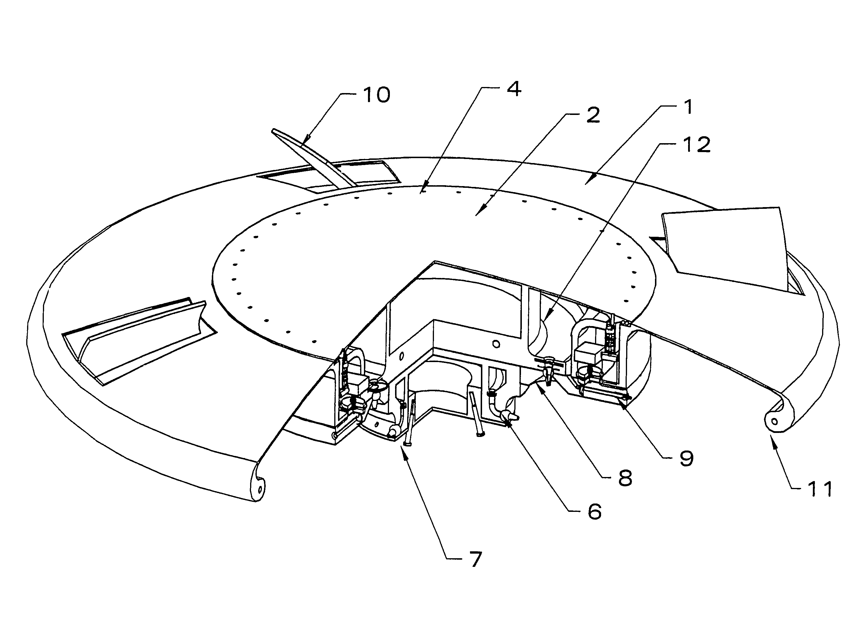
[0036]Embodiments of the present invention relate to an aircraft that is housed entirely within a gyroscope providing the improved flight stability. It introduces the new concept of a sine-wave ring that is used to activate a plurality of pistons which will intake air from above the upper surface of the inner hull configuration and create a negative...


PUM

PropertyMeasurementUnit
heightaaaaaaaaaa
rotational forcesaaaaaaaaaa
radiusaaaaaaaaaa

Abstract

An aircraft that is housed within a gyroscope providing for improved flight stability that includes an inner hull which remains stationary within a rotating outer hull. A rotating sine-wave ring is used to activate and move a plurality of pistons which will intake air from above the upper surface of the inner hull configuration and create a negative pressure on the aircraft. The craft contains compression chambers which receive the air and which feed the various impeller thrusters which are rotational within three-fourths of a hemisphere.

Description

BACKGROUND OF THE INVENTION[0001]1. Field of the Invention[0002]The present invention relates to vehicles and more particularly to flying vehicles.[0003]2. Description of Related Art[0004]With the current concerns over the polluting of the atmosphere, climatic change, and damage to the ozone layer, a critical look at and solution to the problems is necessary. Today jet planes fly higher than stratocumulus and altostratus clouds and spew polluting material at altitudes that are too high to be easily returned to Earth by rainfall, creating a permanent concealment of dirt that traps too much heat beneath its veil. Also, the intense heat from the rockets and other vehicles of various countries' space programs punch their way into outer space and continually burn off the ozone layer in their flight, inflicting damage that will last for many generations. Furthermore, millions of gallons of petroleum products are burned up daily with the prospect of depleting the world supply within this c...

Claims


Application Information

Patent Timeline
Patent Type & Authority Patents(United States)
IPC IPC(8): B64C29/00
CPCB64C17/06B64C39/001B64C29/0025B64C39/06
Inventor MARTIN, HERBERT
Owner MARTIN HERBERT
Why Eureka
Try Eureka