Multiple link, self-jacking work cart wa002

a work cart and multi-link technology, applied in the direction of sledge wheels, work benches, shelves, etc., can solve the problems of reducing affecting the service life of the work cart, and causing the vibration of the work cart to become amplified, so as to and reduce the vibration of the work cart.

Inactive Publication Date: 2011-07-05
WISE ROBERT W
View PDF23 Cites 17 Cited by
  • Summary
  • Abstract
  • Description
  • Claims
  • Application Information

AI Technical Summary

Benefits of technology

It is a further object of the present invention to provide a mobile work cart as described above wherein a deploying operation of lateral wings or deployable work tables automatically actuates the self-jacking operation to prevent the cart from tipping when heavy objects are placed on the work tables.
The invention achieves the above objects and other objects and advantages that will become apparent from the description which follows by providing a multiple link, self-jacking mobile work cart including a main body generally supported by four wheels. The work cart includes at least one moveable support leg being pivotable between a stowed position and a deployed position to at least partially support the work cart with respect to a work surface such as a workshop floor. The work cart further includes at least one deployable work table pivotally connected to the work cart to enlarge the scope of the work cart and / or provide one or more laterally extending work surfaces for use as infeed / outfeed tables for a table saw, chop saw or other tool in use on a main body of the work cart. Preferably, deployment of the work table from a stowed position to a deployed position motivates an actuator arm having a first end pivotally connected to the work cart. The control arm is itself is connected to a linkage arm having an upper end pivotally connected to the actuator arm and a lower end pivotally connected to the support leg. Finally, in the preferred embodiment a control arm having a lower end pivotally connected to a free end of the actuator arm, and an upper end pivotally connected to the work table operates such that deployment of the work table from the stowed position to the deployed position lowers the moveable support leg into contact with the support surface, such as the workplace floor. In this way, at least some of the weight supported by the work table is transferred to the support leg so as to provide a higher frictionally engagement between the work cart and the floor and so as to suppress vibratory movement, tipping or displacement of the work cart.
In a preferred embodiment of the invention, a projection of the actuator arm through the work table in the deployed condition is outboard of the connection between the control arm upper end and the work table such that downward force on the work table (such as by an object placed thereupon) translates into further downward force on the support leg against the support surface such as the work room floor rather than inward collapsing movement of the actuator arm towards the stowed position. This effect can be achieved by pivotally connecting the upper end of the linkage arm to the actuator arm at a first distance “a” from the actuator arm first end, and connecting a lower end of the linkage arm to the support leg at a second distance “b” from the support leg upper end whereby downward pressure on the deployable work table causes a greater downward force on the distal end of the actuator arm than the corresponding inward force on the distal end of the actuator arm. By providing the first distance “a” greater than the second distance “b,” downward force on the distal end of the actuator arm has a multiplying effect on the rotational torque applied to the upper end of the support leg so as to further force the support leg into the support surface such as the workshop floor. In the preferred embodiments, the control arm and the linkage arm are in the form of yokes and a pair of support legs are provided for each deployable lateral work table and two such work tables are provided. All of the linkages, and the deployable work table are preferably collapsible in the stowed positions such that the work cart can take up as little place in the workshop as possible when not in use, and deployment of the work tables operate the multiple link, self-jacking mechanism to at least partially support weight on the work tables from the workshop floor.

Problems solved by technology

One disadvantage of this prior art design, as well as other prior art designs discussed above, is that when the saw stand is in the extended or raised position, a significant part of the load is borne by the wheels.
While these work benches are well adapted for indoor use on smooth floors (e.g., shop floors), they may transmit induced vibrations from a power tool thereon to a work shop floor through wheels.
On a smooth, flat surface (e.g., a garage floor, hardwood floors, etc.) vibrations from the saw tend to cause minor movement in the wheels, thus allowing undesirable vibrations to become amplified through positive feedback and reverberate through the saw stand.
More significantly, loads placed on the infeed / outfeed tables tend to exacerbate torque applied at the wheels due to the moment effect of the tables on the cart, causing the cart to tip.

Method used


Image

  • Multiple link, self-jacking work cart wa002
  • Multiple link, self-jacking work cart wa002
  • Multiple link, self-jacking work cart wa002

Examples


Embodiment Construction

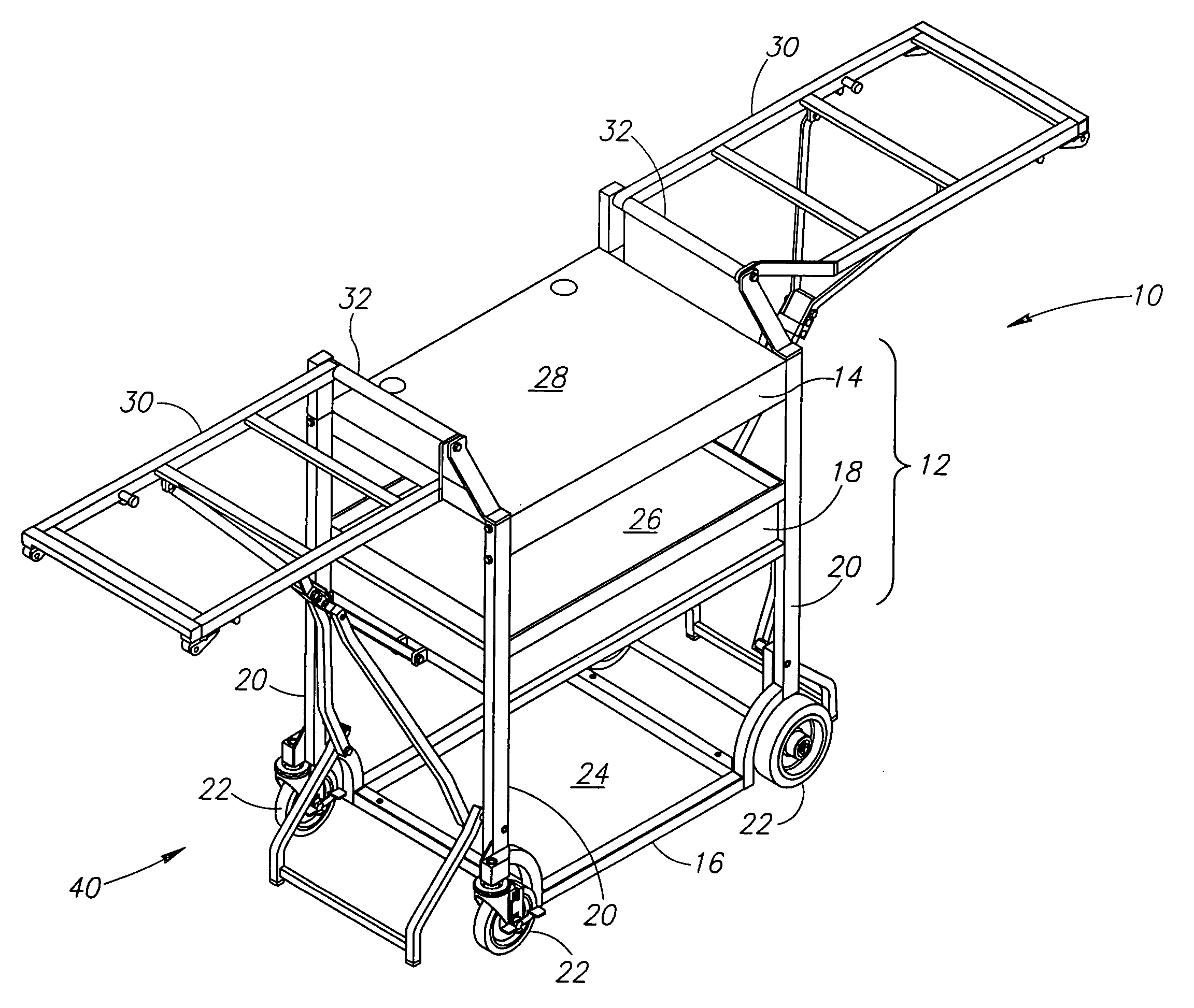
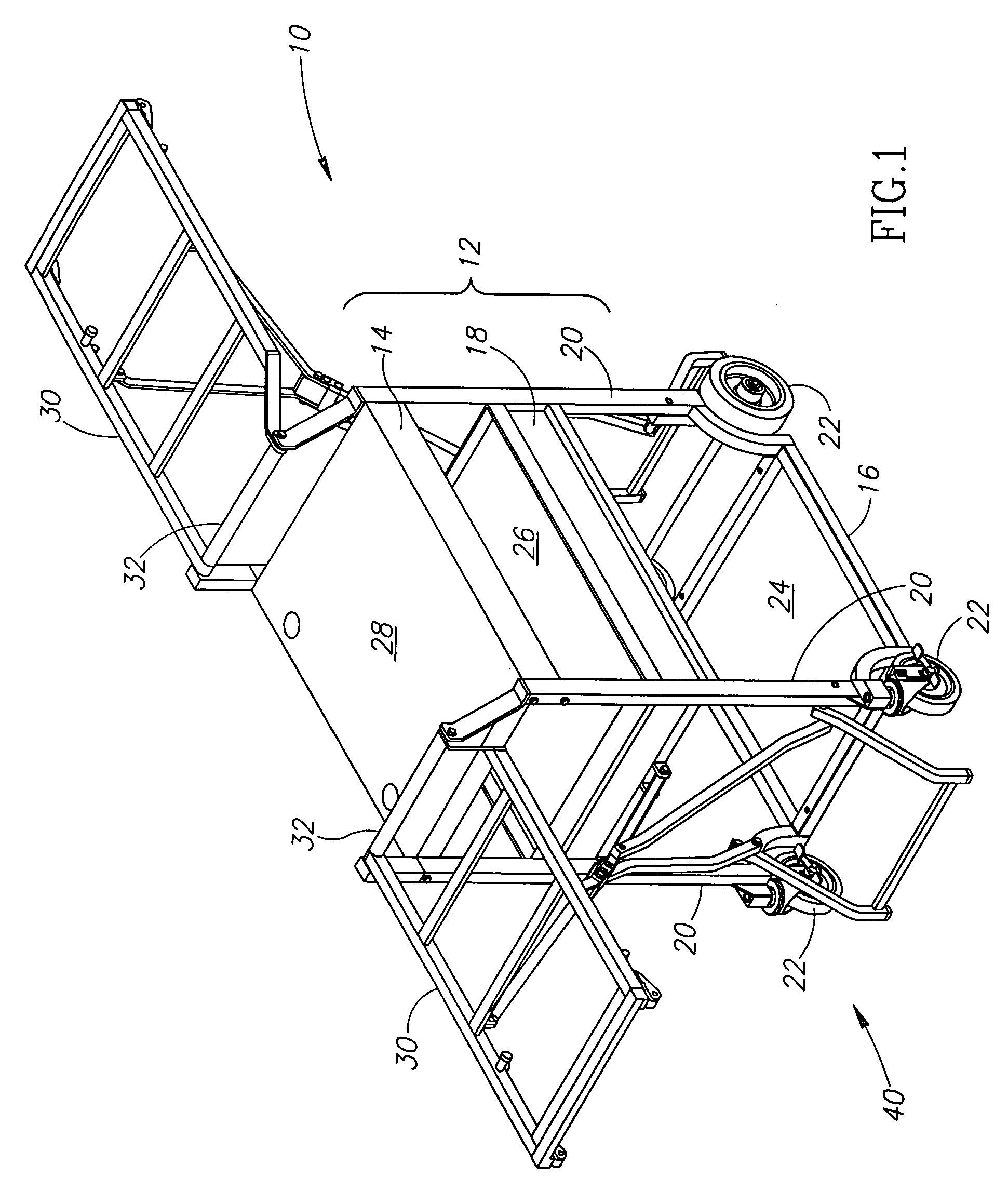
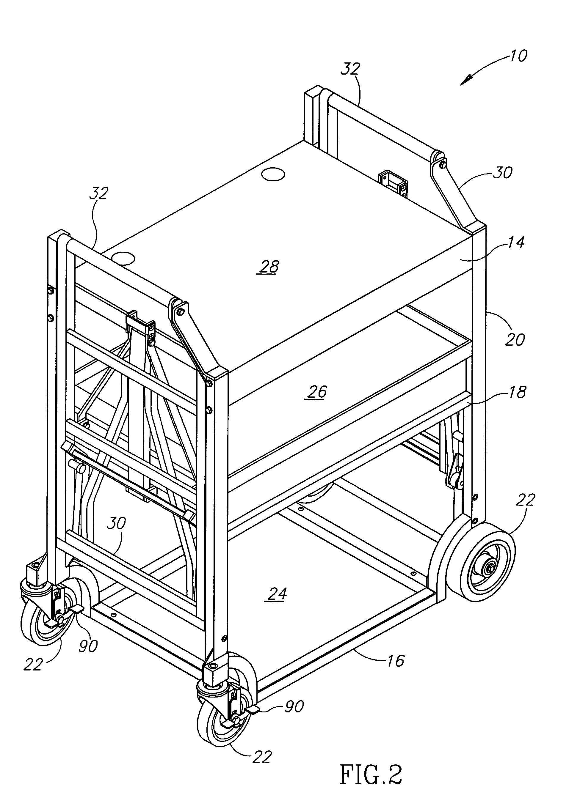
A multiple-linkage, self-jacking wheeled mobile work cart or cart in accordance with the principles of the invention is generally indicated at reference numeral 10 in the various Figures of the attached drawings, wherein numbered elements in the Figures correspond to like numbered elements herein. The cart 10 has a main body generally indicated at reference numeral 12 consisting of an upper portion 14, a lower portion 16 and an intermediate portion 18 interconnected by four vertical stanchions 20 at lateral edges of the main body which is supported by four rotating wheels 22. The lower portion preferably consists of a shelf 24 for placing tools or the like thereon, while the intermediate portion 18 preferably consists of a drawer 26 also adapted for accepting various hand tools. The upper portion 14 preferably incorporates a power tool base 28 adapted to receive a wide variety of power tools such as table saws, chop saws, drill presses, compound sliding miter saws and the like. As i...


PUM


Abstract

A multiple link, self-jacking mobile work cart includes the main body defining upper and lower portions supported by the plurality of rotating wheels. A multiple link, self-jacking mechanism is provided in connection with two laterally deployable work tables which can serve as infeed / outfeed tables for a power tool or the like supported by the main body of the cart. The multiple link mechanism includes an actuator arm, a linkage arm, a control arm and moveable support legs all pivotally connected to one another such that when the work tables are deployed, substantial weight placed on the tables is transferred to the support legs, rather than the wheels which support the main body.

Description

TECHNICAL FIELDThe invention relates to mobile stands for powered tools. More specifically, the invention relates to four wheel, mobile stands for power tools such as miter saws, chop saws, task saws, compound sliding circular saws and the like of the type having lateral, attached infeed / outfeed tables.BACKGROUND OF THE INVENTIONPortable, wheeled tool carts have been available for some time. One such prior art tool cart is shown and described by Wise, the inventor herein, in U.S. Pat. No. 5,642,898 issued Jul. 1, 1997. Additional tool carts have been described in the patent literature. For instance, U.S. Pat. No. 4,955,941, issued Sep. 11, 1990, to Rousseau, describes a support table for a bench saw. U.S. Pat. No. 4,230,329, issued Oct. 28, 1980 to Johnson, describes a mobile cart. U.S. Pat. No. 5,161,590, issued Nov. 10, 1992, to Otto, describes a miter saw table apparatus. U.S. Pat. No. 5,255,724; issued Oct. 26, 1993, to Butke, describes an adjustable extension assembly. A brochu...

Claims


Application Information

Patent Timeline
Patent Type & Authority Patents(United States)
IPC IPC(8): B62B3/02
CPCB25H1/04B62B3/02B62B2301/00
Inventor WISE, ROBERT W.
Owner WISE ROBERT W
Why Eureka
Try Eureka