Transmission-controlled window glazing

Active Publication Date: 2011-07-05
AIRBUS OPERATIONS GMBH
View PDF14 Cites 76 Cited by
  • Summary
  • Abstract
  • Description
  • Claims
  • Application Information

AI Technical Summary

Benefits of technology

[0015]The application of window glazing according to the invention in an airplane or motor vehicle is viewed as particularly advantageous, s

Problems solved by technology

However, no other indications are made with respect to generating a glazing

Method used


Image

  • Transmission-controlled window glazing
  • Transmission-controlled window glazing
  • Transmission-controlled window glazing

Examples


Embodiment Construction

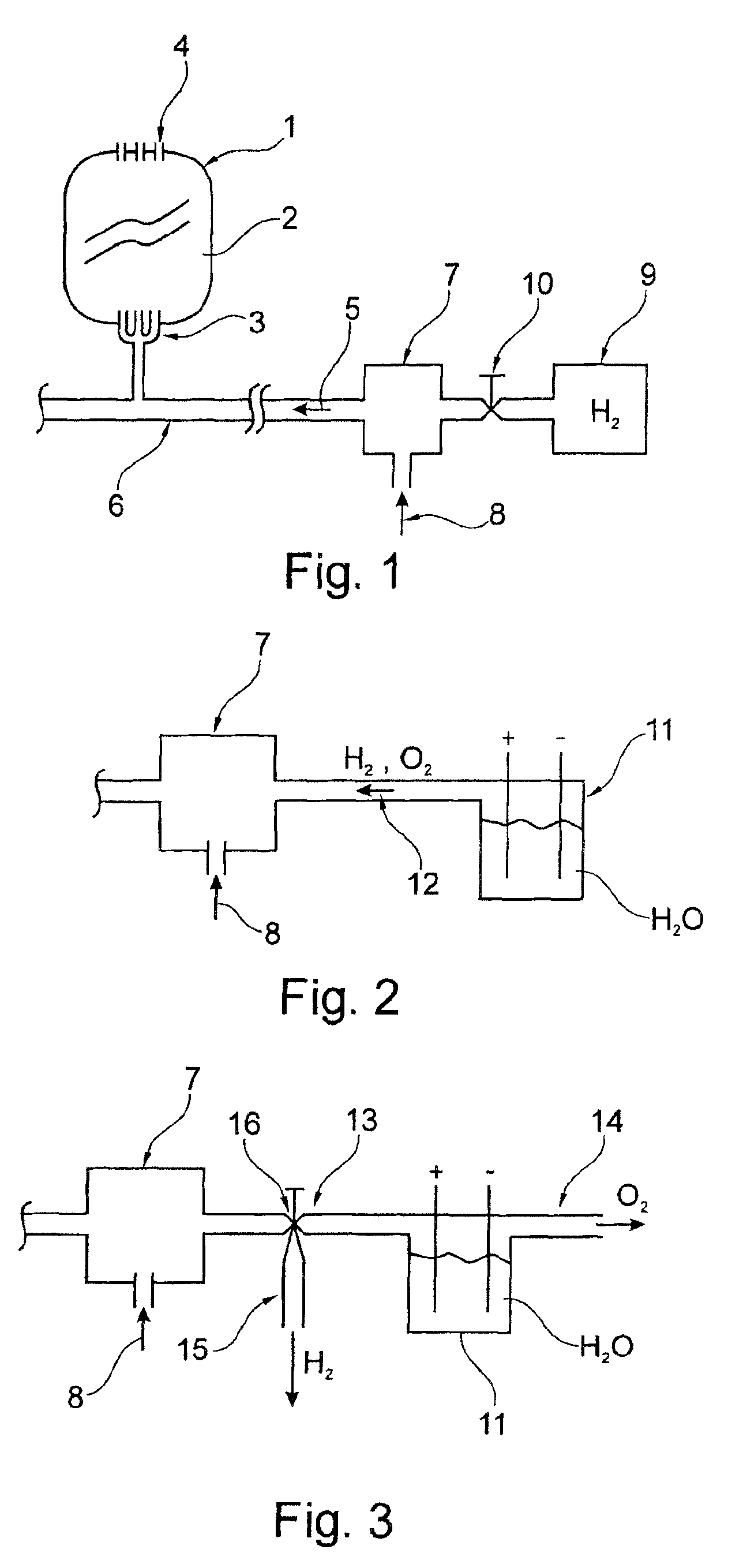
[0024]FIG. 1 depicts a simplified section through a window glazing, which in the exemplary embodiment comprises two panes that enclose a gap 2. It is also just as possible to use a multi-pane glazing in this location. The gap 2 additionally exhibits a number of openings 3 for introducing the flushing gas 5. A number of additional openings 4 are usually arranged on the opposite side to divert the flushing gas in order to achieve a uniform flow through the gap.

[0025]Window glazing of this kind is used in motor vehicles and airplanes subject to special climatic conditions during operation. This type of window glazing, which exhibits two or more panes, has become known in particular in airplanes. The panes in such window glazing can be provided on the sides facing the gap 2 with a transparent coating, whose degree of transmission can be altered by varying electrical or electrochemical parameters. Know in particular are coatings whose transmission changes as a function of the hydrogen co...


PUM


Abstract

The invention relates to a window glazing comprising at least two window panes with an intermediate ventilated space arranged therebetween, wherein at least one window pane is provided with a layer which is arranged on the interior side therefore and whose transmission is controllable. More specifically, said invention relates to a multilayer glazing comprising corresponding intermediate spaces in which a sweeping gas circulates, wherein said sweeping gas consists of a mixture of air and other gaseous components in which the sweeping gas content is adjustable.

Description

CROSS-REFERENCE TO RELATED APPLICATIONS[0001]This is a national phase entry under 35 U.S.C. §371 of International Application No. PCT / EP2006 / 008290 filed Aug. 23, 2006, published in German, which claims the benefit of the filing date of German Patent Application No. 10 2005 039 838.3 filed Aug. 23, 2005, the entire disclosures of each application are hereby incorporated herein by reference.BACKGROUND OF THE INVENTION[0002]The invention relates to a window glazing comprising at least two panes with a ventilated gap, wherein the inside of at least one of the panes is provided with a layer with a controllable transmission.[0003]An internally ventilated glazing for airplanes is known from GB 640,554. This glazing consists of two panes consisting of glass or plastic, and mounted spaced apart. The resultant gap is flushed with dried air, so that the dual pane remains transparent under all temperature conditions encountered during operation.[0004]Known from EP 0 338 876 B1 is an electrochr...

Claims


Application Information

Patent Timeline
IPC IPC(8): G02B7/18
CPCE06B3/6722G02F2202/34
Inventor SCHERER, THOMAS
Owner AIRBUS OPERATIONS GMBH
Why Eureka
Try Eureka