Variable capacity compressor

a compressor and variable capacity technology, applied in the direction of positive displacement liquid engines, reciprocating piston engines, positive displacement engines, etc., to achieve the effects of improving controllability of compressors, high controllability of compressors, and increasing sliding friction

Inactive Publication Date: 2011-07-05
CALSONIC KANSEI CORP
View PDF7 Cites 7 Cited by
  • Summary
  • Abstract
  • Description
  • Claims
  • Application Information

AI Technical Summary

Benefits of technology

[0008]The present invention is provided to solve the problem. An object of the present invention is to provide a no-sleeve type variable capacity compressor capable of preventing an increased sliding friction caused by torsion load.
[0010]According to the present invention, when the swash plate receives a compression reaction force and leans out of its inclination direction, the first linking pin leans to and contacts with an inner face of the bearing hole at two points and the second linking pin leans to and contacts with an inner face of the bearing hole at two points, so as to receive the compression reaction force that applied to the swash plate. With this structure, the link member is not pressed against the pair of the arms of the rotating member at two points and against the pair of the arms of the tilting member at two points so as not to be in a wedged state. This prevents such a wedged state causing an increased sliding friction, so that the controllability of the compressor is improved.
[0011]When an excessive compression reaction force, which is greater than a predetermined value, is applied to the swash plate, the first linking pin contacts with two points on the inner face of the bearing hole and the second linking pin contacts with two points on the inner faces of the bearing hole, and also a flexure is caused in at least one of the members constituting the link mechanism (at least one of the pair of arms of the rotating member, the pair of arms of the tilting member, the link member, the first linking pin, and the second linking pin), so that the degree of the incarnation of the tilting member further increases.
[0012]In this case, the compression reaction force can be supportively received in the tilting guide hole since the drive shaft contacts with two points on the pair of tilting guide faces in the tilting guide hole before the link member contacts with two points on the pair of arms of the tilting member and the pair of the arms of the rotating member. The link member is thus prevented from contacting with the pair of arms at two points even when an excessive compression reaction force, which is greater than a predetermined value, is applied. This prevents the link member from becoming wedged, so that the high controllability of the compressor is maintained.

Problems solved by technology

The above problem can occur in a variable capacity compressor in that a swash plate is attached to a drive shaft via a sleeve and also in a no-sleeve type variable capacity compressor in that a swash plate is directly attached to a drive shaft.

Method used


Image

  • Variable capacity compressor
  • Variable capacity compressor
  • Variable capacity compressor

Examples


Embodiment Construction

[0031]A variable capacity compressor of an embodiment of the present invention will be described with reference to the accompanying drawings.

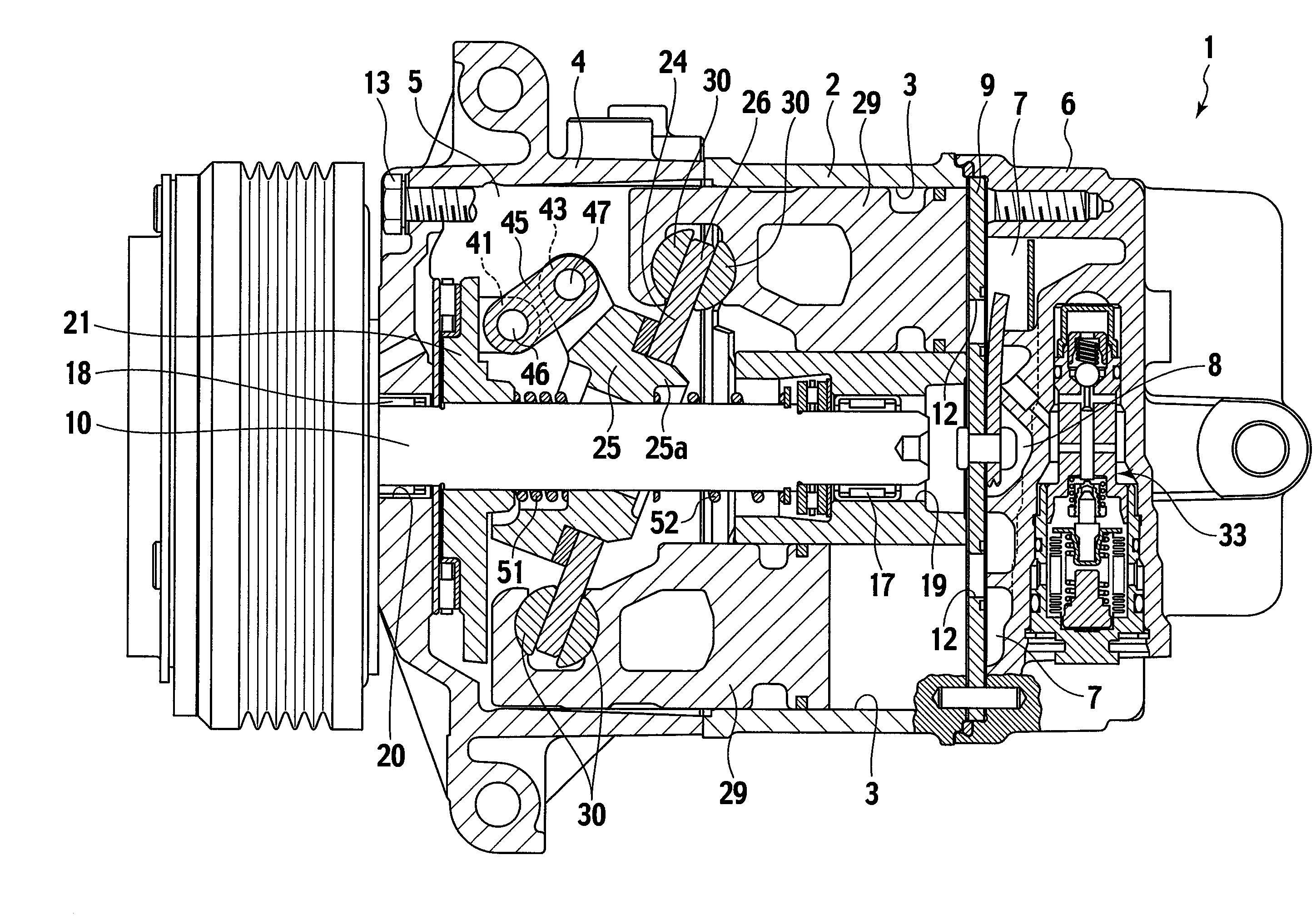
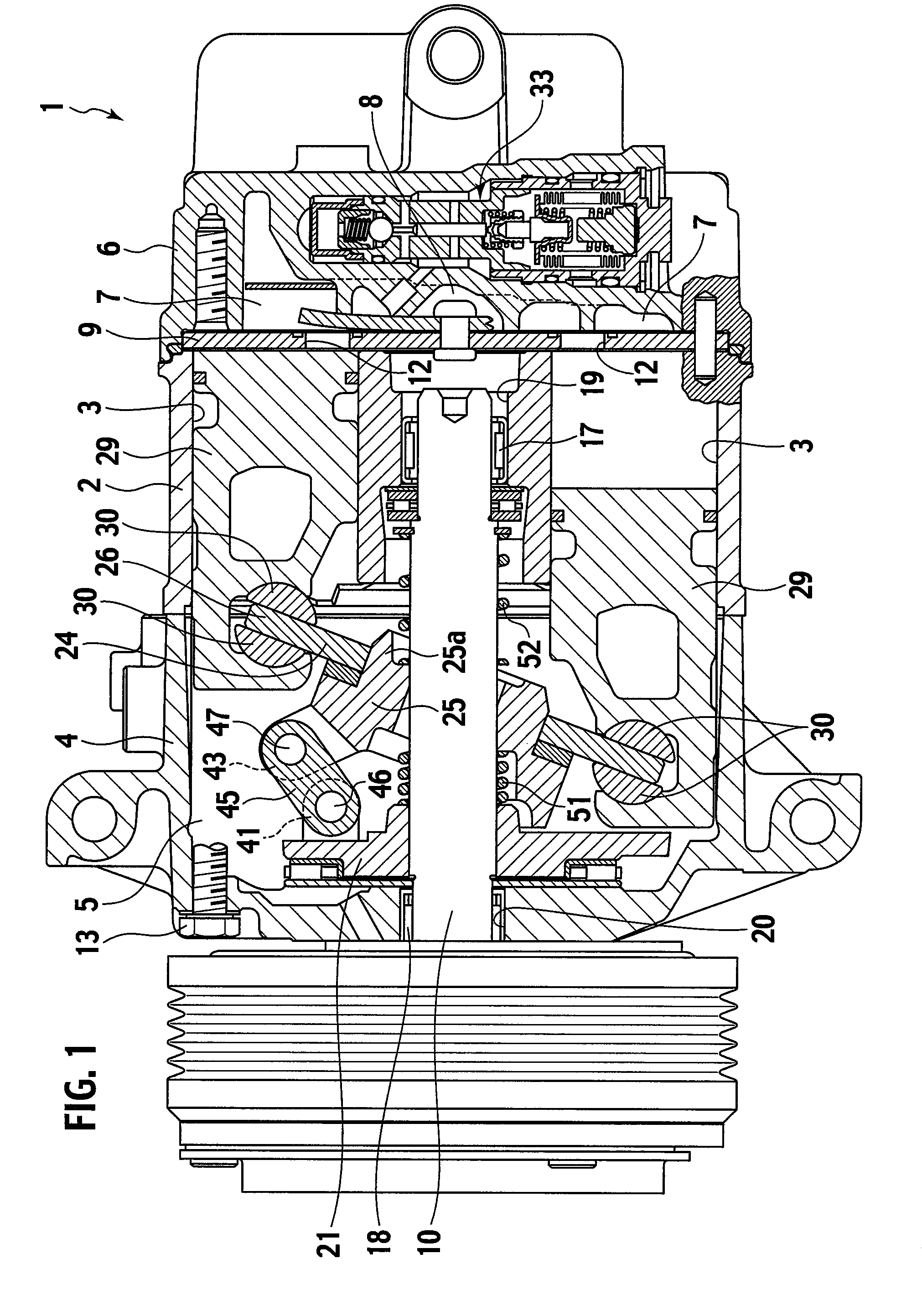
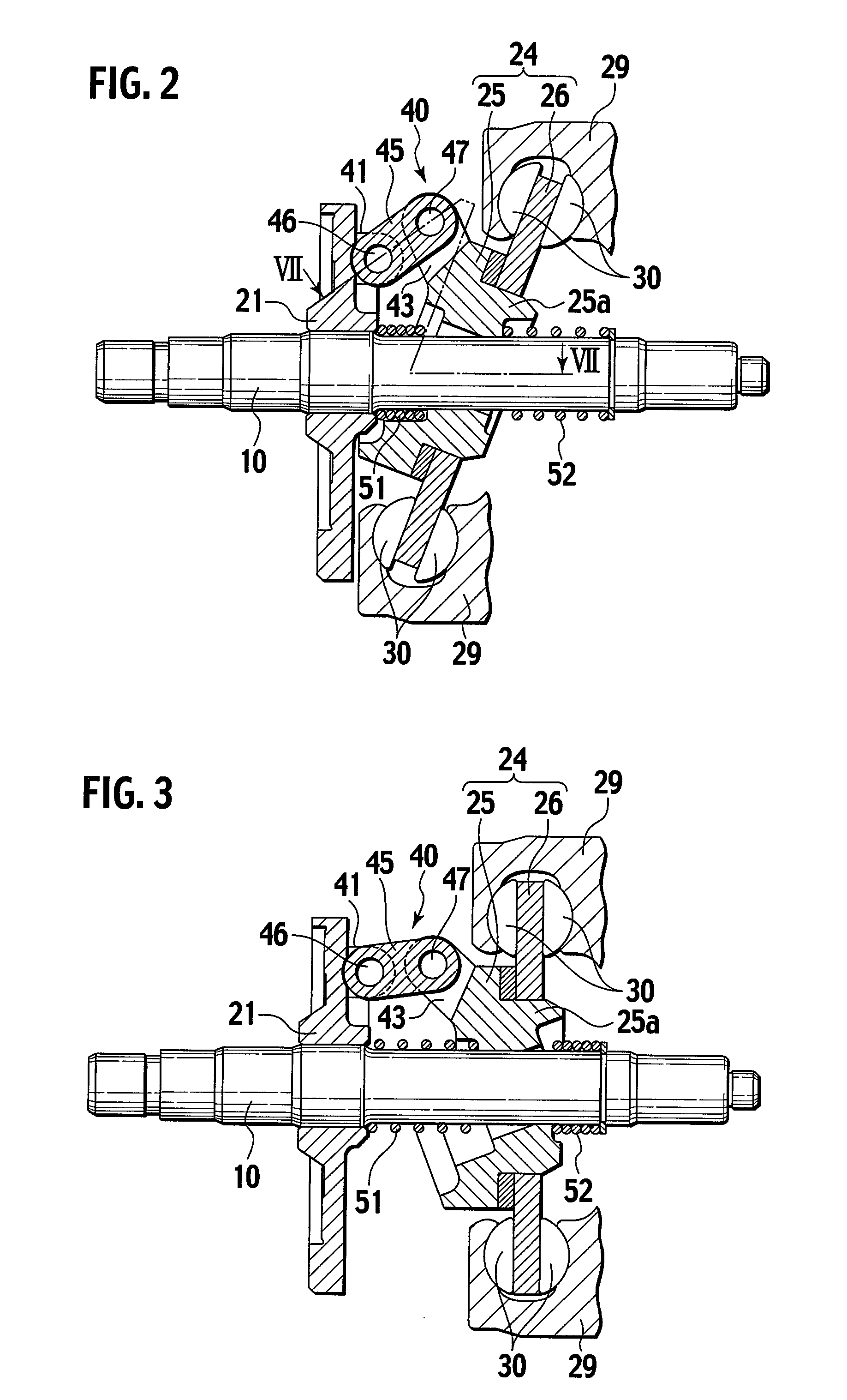
[0032]FIG. 1 is a cross-sectional view of the entire variable capacity compressor, FIG. 2 shows an inclination of a swash plate in a full stroke condition, and FIG. 3 shows an inclination of the swash plate in a no-stroke condition.

[0033]As shown in FIG. 1, the variable capacity compressor 1 includes a cylinder block 2 having a plurality of cylinder bores 3 (FIG. 2) placed evenly spaced apart in a circumferential direction, a front housing 4 attached to a front end of the cylinder block 2 and having a crank chamber 5 therein, and a rear housing 6 attached to a rear end of the cylinder block 2 via a valve plate 9 and having a suction chamber 7 and a discharge chamber 8 therein. The cylinder block 2, the front housing 4, and the rear housing 6 are fixedly connected to one another by a plurality of bolts 13 so as to make up a housing of the compre...


PUM


Abstract

The first maximum inclination angle θ1 is a maximum inclination angle of a link member 45 allowed by a clearance between a slit 41s of a rotor 21 and one end 45a of the link member 45; the second maximum inclination angle θ2 is a maximum inclination angle of the link member 45 allowed by a clearance between a slit 43s of a swash plate 24 and the other end 45b of the link member 45; the third maximum inclination angle θ3 is a maximum inclination angle of a first linking pin 46 allowed by a clearance between the first linking pin 46 and a first bearing hole 41a; the fourth maximum inclination angle θ4 is a maximum inclination angle of a second linking pin 47 allowed by a clearance between the second linking pin 47 and a second bearing hole 43a; and the fifth maximum inclination angle θ5 is a maximum inclination angle of the swash plate 24 with respect to the drive shaft 10 allowed by a clearance between the drive shaft 10 and a pair of the tilting guide faces 37, 37. Relations (θ3+θ4)<θ5<θ1, θ2 are established.

Description

TECHNICAL FIELD[0001]The present invention relates to a variable capacity compressor.BACKGROUND ART[0002]A conventional variable capacity compressor includes a drive shaft, a rotor fixed to the drive shaft to rotate integrally with the drive shaft, a swash plate which is tiltably attached to the drive shaft, and a link mechanism provided between the rotor and the swash plate (see, for example, Japanese Patent Application Laid-Open Publication No. 10-176658). The link mechanism permits the inclination angle of the swash plate to change while transferring torque from the rotor to the swash plate. When the inclination angle of the swash plate is changed, strokes of pistons are changed so that discharge rate of the compressor is changed.[0003]FIG. 17 is a view of a link mechanism disclosed in Publication No. 10-176658.[0004]The link mechanism in FIG. 17 includes a pair of rotor arms 145, 146 which extend from a rotor 140 toward a swash plate 141 and face to each other, a single swash pl...

Claims


Application Information

Patent Timeline
Patent Type & Authority Patents(United States)
IPC IPC(8): F04B1/12
CPCF04B27/1072
Inventor HIRABAYASHI, YUICHIUSUI, KEIGO
Owner CALSONIC KANSEI CORP
Why Eureka
Try Eureka