
Remote operation system

a remote control and operation system technology, applied in the field of remote control operation systems, can solve the problems of not being able to operate the television receiver using a single remote control unit, not being able to confirm whether the stored remote control data is available, and not being able to operate the television receiver. , to achieve the effect of reducing cost and improving ease of us

Inactive Publication Date: 2011-07-05
FUNAI ELECTRIC CO LTD
View PDF12 Cites 33 Cited by
  • Summary
  • Abstract
  • Description
  • Claims
  • Application Information

AI Technical Summary

Benefits of technology

Enables operation of auxiliary devices like television receivers using a remote control unit intended for DVD players, reducing the need for multiple remote controls, simplifying use, and lowering costs by allowing a single remote control unit to manage both devices, while ensuring correct remote control code settings.

Problems solved by technology

However, it is not possible to confirm whether the stored remote control data is the desired remote control data set at the remote control transmitter.
In this related technology, when, for example, a television receiver is connected as a display apparatus to a visual apparatus such as, for example, a DVD player, it is not possible to also operate the television receiver using the single remote control unit belonging to the DVD player.
It is therefore no longer possible to operate the television receiver if the remote control unit belonging to the television receiver is lost.
This means that in this related technology also, it is not possible to operate a television receiver using a single remote control unit belonging to a DVD player when, for example, a television receiver is connected as a display apparatus to, for example, a DVD player taken as a visual apparatus.
It is therefore also not possible to then operate the television receiver when the remote control unit belonging to the television receiver is lost.

Method used


Image

  • Remote operation system
  • Remote operation system
  • Remote operation system

Examples


Embodiment Construction

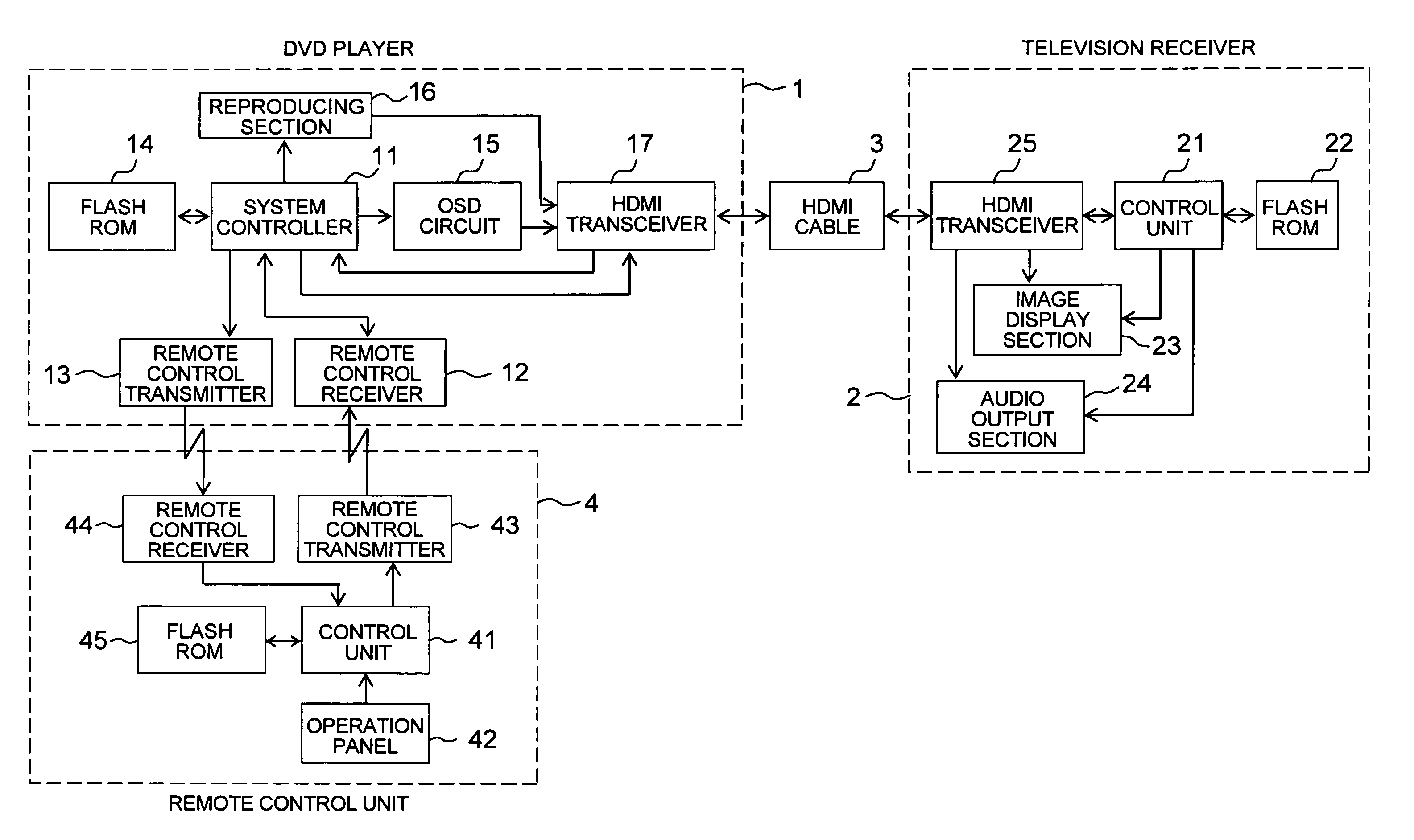
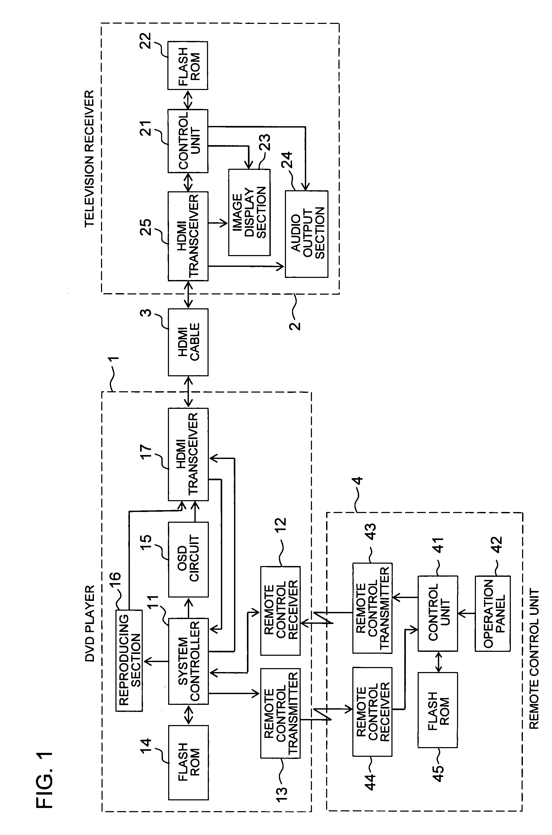
[0018]An embodiment of the present invention will now be described with reference to the attached drawings. FIG. 1 is a block view showing a configuration for a remote operation system of an embodiment of the present invention. In this embodiment, a description is given taking a DVD player as a main apparatus to be operated (hereinafter referred to simply as “main apparatus”) and a television receiver as an auxiliary apparatus to be operated (hereinafter referred to simply as “auxiliary apparatus”). However, the present invention is by no means limited in this respect. For example, the main apparatus may also be a DVD recorder, hard disk recorder, or another audio visual apparatus, and the auxiliary apparatus may be a monitor apparatus provided with an image display unit and audio output unit.

[0019]In FIG. 1, a DVD player 1 is provided with a system controller 11 including a microcomputer etc. for controlling the player as a whole, a remote control receiver 12 for receiving remote c...


PUM


Abstract

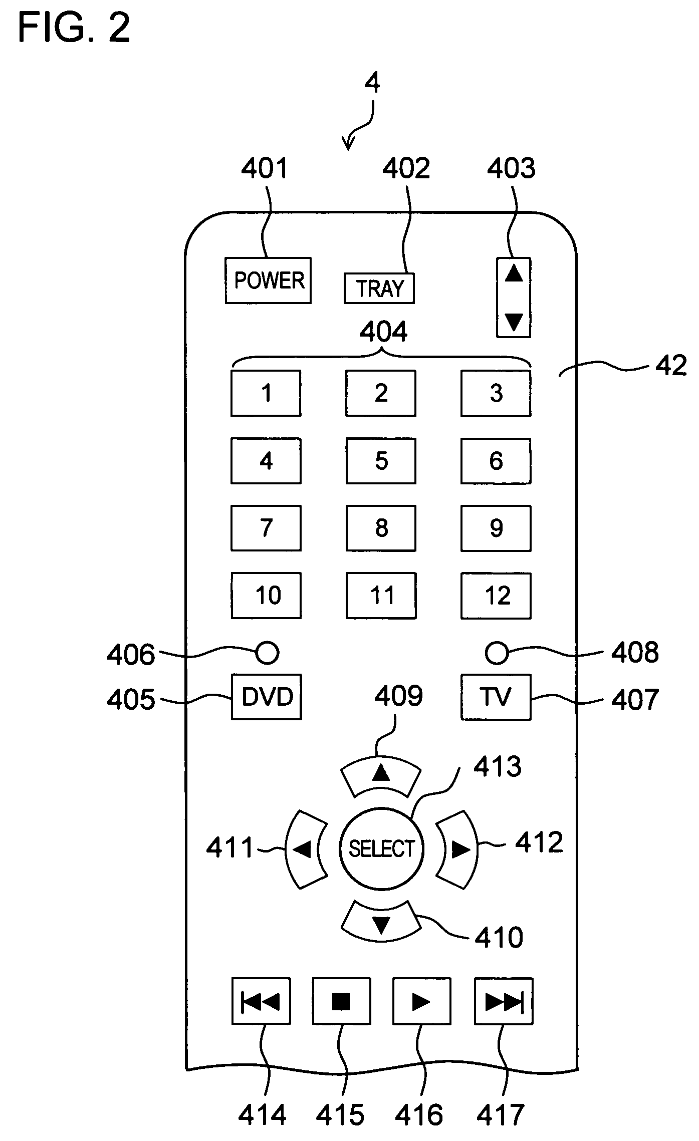
When a television receiver is connected to a DVD player via an HDMI cable, HDMI authentication is carried out. EDID data is then acquired from the television receiver and a manufacturer name is determined. When the manufacturer name is determined to be, for example, “company A”, a table indicating a correspondence relationship of manufacturer names and remote control codes is referred to and remote control codes corresponding to the determined company A are selected. The selected remote control codes are then transmitted after selection of remote control codes of the company A is carried out. Remote control codes corresponding to the manufacturer name of the company A received from the DVD player are then stored in a memory in a manner corresponding to operation key numbers allocated in advance to a plurality of operation keys at a remote control unit.

Description

[0001]This application is based on Japanese Patent Application No. 2006-278327 filed on Oct. 12, 2006, the contents of which are hereby incorporated by reference.BACKGROUND OF THE INVENTION[0002]1. Field of the Invention[0003]The present invention relates to a remote operation system where a main apparatus (for example, a digital video disc (DVD) player) and another auxiliary apparatus (for example, a television receiver) connected to the main apparatus via a cable of a predetermined interface (for example, a high definition multimedia interface (HDMI)) can be operated remotely using a single remote control unit.[0004]2. Description of Related Arts[0005]Apparatuses that are operated using a remote control unit such as DVD players that playback information recorded on a DVD that is an optical disc, DVD recorders that record / playback information to and from a DVD, television receivers, or the like can each be remotely operated by their own respective remote control units. The number o...

Claims


Application Information

Patent Timeline
Patent Type & Authority Patents(United States)
IPC IPC(8): G05B11/01G08C19/16H04L17/02H04N5/44G09G5/00G06F3/02G06F13/00H04N5/00H04N7/173H04N21/435H04N21/4363H04Q9/00
CPCG08C19/28H04N5/4403H04N21/4117H04N21/42207H04N21/42226H04N21/43635G08C2201/20H04N2005/4407H04N2005/4435H04N21/41265H04N21/42204
Inventor KAWAKITA, MITSURU
Owner FUNAI ELECTRIC CO LTD
Learn More