Disk drive to reduce head instability

a technology of disk drives and head surfaces, applied in the field of disk drives, can solve the problems of head instability, carbon wear on the slider surface, and degradation of lubricant on the disk media surface,

Inactive Publication Date: 2011-07-05
WESTERN DIGITAL TECH INC
View PDF15 Cites 140 Cited by
  • Summary
  • Abstract
  • Description
  • Claims
  • Application Information

AI Technical Summary

Problems solved by technology

Unfortunately, the square-waved DFH voltage often causes head instability during touchdown detection.
The head instability often results in false touchdown detection followe

Method used


Image

  • Disk drive to reduce head instability
  • Disk drive to reduce head instability
  • Disk drive to reduce head instability

Examples


Embodiment Construction

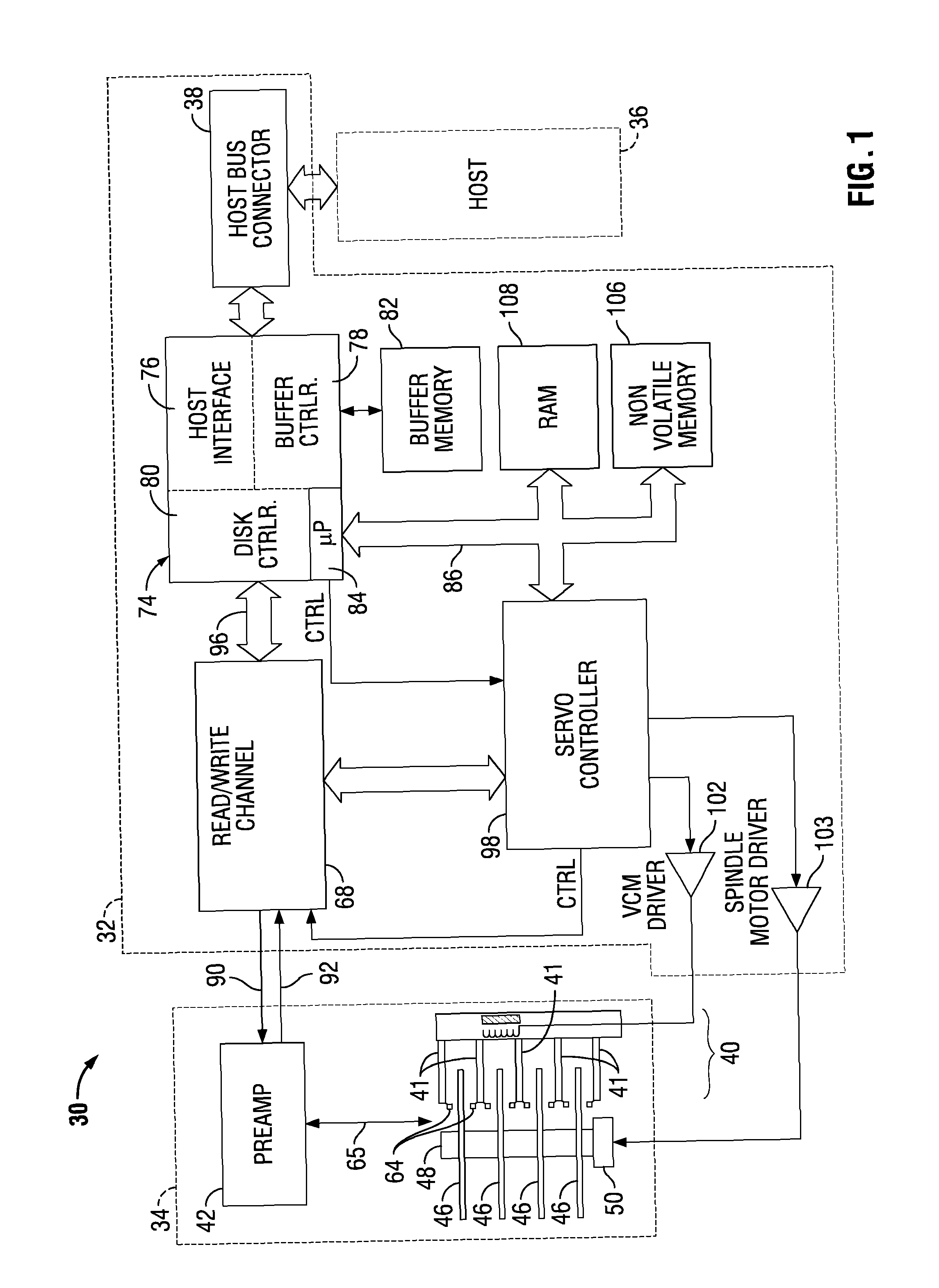
FIG. 1 shows a simplified block diagram of a disk drive 30, in which embodiments of the invention may be practiced. Disk drive 30 comprises a Head / Disk Assembly (HDA) 34 and a controller printed circuit board assembly (PCBA) 32. Host 36 may be a computing device such as a desktop computer, a laptop computer, a server computer, a mobile computing device (e.g. PDA, camera, cell-phone, etc.), or any type of computing device. Alternatively, host 36 may be a test computer that performs calibration and testing functions as part of the disk drive manufacturing process. Disk drive 30 may be of a suitable form factor and capacity for computers or for smaller mobile devices (e.g. a small form factor (SFF) disk drive).

HDA 34 comprises: one or more disks 46 for data storage; a spindle motor 50 for rapidly spinning each disk 46 (four shown) on a spindle 48; and an actuator assembly 40 for moving a plurality of heads 64 over each disk 46. Actuator assembly 40 includes a plurality of actuator arms...


PUM


Abstract

A disk drive to reduce head instability during disk drive manufacturing is disclosed. The disk drive comprises: a disk; a dynamic flying height (DFH) read/write head; a flying height actuator to control the spacing between the DFH read/write head and the disk; and a controller. The controller controls operations in the disk drive including applying a sloped increasing power between a first voltage and a second voltage to move the DFH read/write head towards the disk.

Description

BACKGROUNDA huge market exists for disk drives for mass-market computing devices such as desktop computers and laptop computers, as well as small form factor (SFF) disk drives for use in mobile computing devices (e.g. personal digital assistants (PDAs), cell-phones, digital cameras, etc.). To be competitive, a disk drive should be relatively inexpensive and provide substantial capacity, rapid access to data, and reliable performance.Disk drives typically employ a moveable head actuator to frequently access large amounts of data stored on a disk. One example of a disk drive is a hard disk drive. A conventional hard disk drive has a head disk assembly (“HDA”) including at least one magnetic disk (“disk”), a spindle motor for rapidly rotating the disk, and a head stack assembly (“HSA”) that includes a head gimbal assembly (HGA) with a moveable transducer head for reading and writing data. The HSA forms part of a servo control system that positions the moveable transducer head over a pa...

Claims


Application Information

Patent Timeline
IPC IPC(8): G11B21/02G11B27/36
CPCG11B5/6005G11B5/6076G11B5/6064
Inventor XU, JIANFENGKANG, SOO-CHOONSAITO, KAZUHIROZHAO, HONGCHAO TIM
Owner WESTERN DIGITAL TECH INC
Why Eureka
Try Eureka