
Pressure transducer employing a micro-filter and emulating an infinite tube pressure transducer

a technology of pressure transducer and micro-filter, which is applied in the direction of fluid pressure measurement, pressure difference measurement between multiple valves, instruments, etc., can solve the problems and achieve the effect of reducing the overall size and mass of the device and constant cross-section area

Inactive Publication Date: 2011-07-12
KULITE SEMICON PRODS
View PDF4 Cites 10 Cited by
  • Summary
  • Abstract
  • Description
  • Claims
  • Application Information

AI Technical Summary

Benefits of technology

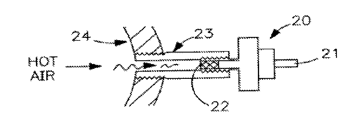
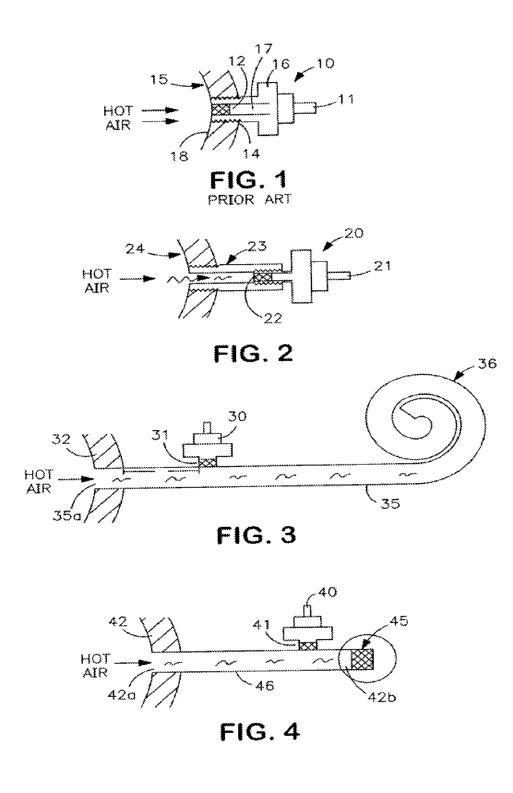
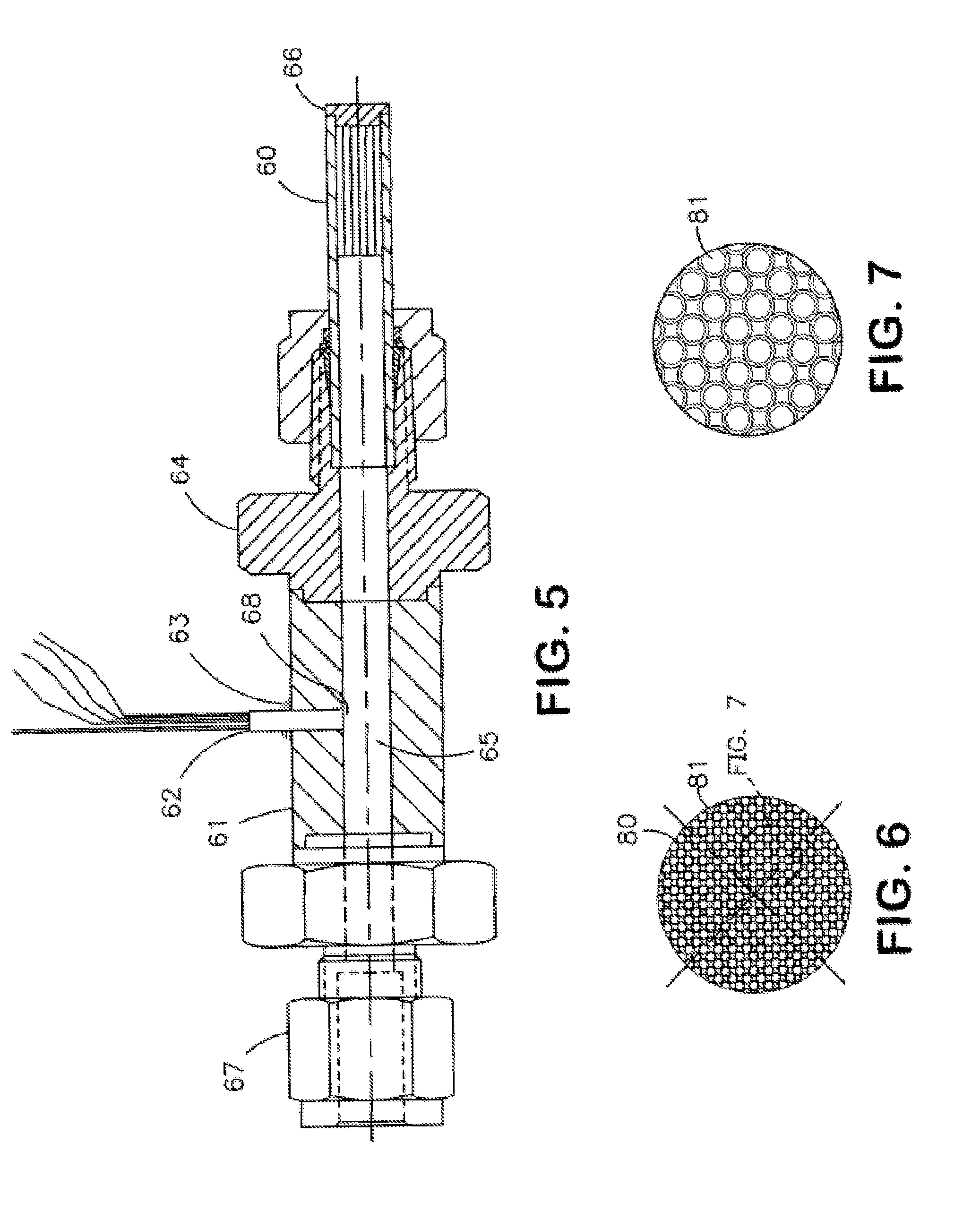
[0007]The various embodiments of the present invention include an elongated tube having a first end adapted to receive an incoming pressure source and a second end wherein a micro-filter, operative to substantially dampen or absorb incoming acoustic waves, is disposed. The elongated tube may have a constant cross-section area or may taper from a first cross-section area at the first end to a second, smaller, cross-section area at the second end. Additionally, the elongated tube may be independent or machined into a support block. Further, the elongated tube may be convoluted to reduce the overall size and mass of the device. The elongated tube may also have a mounting surface positioned near the first end wherein a pressure transducer assembly may be mounted and adapted to measure the pressure of the incoming pressure source.

Problems solved by technology

Further, the elongated tube may be convoluted to reduce the overall size and mass of the device.

Method used


Image

  • Pressure transducer employing a micro-filter and emulating an infinite tube pressure transducer
  • Pressure transducer employing a micro-filter and emulating an infinite tube pressure transducer
  • Pressure transducer employing a micro-filter and emulating an infinite tube pressure transducer

Examples


Embodiment Construction

[0022]Referring to FIG. 1, there is shown a prior art technique depicting a typical installation which is employed in the aerodynamics industry. In FIG. 1, reference numeral 15 represents a gas turbine casing. The gas turbine casing is typically found in a gas turbine engine. The operation of such an engine is attendant with extremely high temperatures which are directed to the casings. There is shown a transducer 10 which is mounted on a housing 16. Housing 16 is threaded and essentially threads into a threaded aperture which is formed in the turbine casing 15. Located remote from the transducer 10 is a sensing diaphragm 12. The sensing diaphragm 12 as seen in FIG. 1 is responsive to the pressure created by the hot air gases associated with the turbine which therefore causes the diaphragm 12 to deflect and produces a pressure response from the transducer which is coupled thereto via the tube cavity 17. The cable 11 directs the output from the transducer 16 to various monitoring equ...


PUM

PropertyMeasurementUnit
temperaturesaaaaaaaaaa
temperatureaaaaaaaaaa

Abstract

It is an objective of the present invention to provide a pressure transducer assembly for measuring pressures in high temperature environments that employs an elongated tube which is terminated at one end by an acoustic micro-filter. The micro-filter has a plurality of apertures extending from one end to the other end, each aperture is of a small diameter as compared to the diameter of the transducer and the damper operates to absorb acoustic waves impinging on it with limited or no reflection. To improve the absorption of acoustic waves, the elongated tube may be tapered and / or mounted to a support block and further convoluted to reduce the overall size and mass of the device. A pressure transducer with a diaphragm flush may be mounted to the elongated tube and extend through to the inner wall of the tube. Hot gases propagate through the elongated tube and their corresponding pressures are measured by the transducer. The acoustic filter operates to absorb acoustic waves resultant from the hot gases, therefore enabling the pressure transducer to be mainly responsive to high frequency waves associated with the gas turbine operation.

Description

CROSS-REFERENCE TO RELATED APPLICATIONS[0001]This application is a continuation-in-part claiming priority under 35 U.S.C. §120 to U.S. patent application Ser. No. 12 / 315,614, entitled “PRESSURE TRANSDUCER EMPLOYING A MICRO-FILTER AND EMULATING AN INFINITE TUBE PRESSURE TRANSDUCER,” filed Dec. 4, 2008, which is not abandoned and is a continuation application claiming priority under 35 U.S.C. §120 to U.S. Pat. No. 7,484,415, entitled “PRESSURE TRANSDUCER EMPLOYING A MICRO-FILTER AND EMULATING AN INFINITE TUBE PRESSURE TRANSDUCER,” issued on Feb. 3, 2009, all of which are incorporated by reference in their entirety as if fully set forth herein.TECHNICAL FIELD[0002]This invention relates to pressure transducers and more particularly to a pressure transducer incorporating a micro-filter replacing the prior art infinite tube.BACKGROUND[0003]Aerodynamic engineers have long desired to measure high frequency flow and pressure disturbances in gas turbine engines and aircraft wings. The capabi...

Claims


Application Information

Patent Timeline
Patent Type & Authority Patents(United States)
IPC IPC(8): G01L9/00
CPCG01L19/0609G01L19/0681Y10T29/49007Y10T29/49005
Inventor KURTZ, ANTHONY D.KURTZ, LEGAL REPRESENTATIVE, NORASHANG, TONGHUOHURST, ADAM
Owner KULITE SEMICON PRODS
Learn More