Supercharge Your Innovation With Domain-Expert AI Agents!

Turbine rotor blade and method of assembling the same

a technology of turbine rotor blades and rotor blades, which is applied in the direction of liquid fuel engines, vessel construction, marine propulsion, etc., can solve the problems of compressed stresses on the upper surface of the platform, shorten the useful life of the rotor blade, and compress thermal stresses on the platform

Active Publication Date: 2011-07-12
GENERAL ELECTRIC CO
View PDF16 Cites 26 Cited by
  • Summary
  • Abstract
  • Description
  • Claims
  • Application Information

AI Technical Summary

Benefits of technology

"The patent describes a method and assembly for a gas turbine engine rotor blade. The rotor blade has a shank, an airfoil, and a removable platform that is attached to the shank using a friction fit. The technical effect of this invention is to provide a more efficient and flexible way to assemble a gas turbine engine rotor blade assembly."

Problems solved by technology

Over time, thermal strain generated by such temperature gradients may induce compressive thermal stresses to the platform.
Over time, the increased operating temperature of the platform may cause platform oxidation, platform cracking, and / or platform creep deflection, which may shorten the useful life of the rotor blade.
However, the cooling passages may introduce a thermal gradient into the platform which may cause compressed stresses to occur on the upper surface of the platform region.
Moreover, because the platform cooling holes are not accessible to each region of the platform, the cooling air may not be uniformly directed to all regions of the platform.
Since the platform is formed integrally with the dovetail and the shank, any damage that occurs to the platform generally results in the entire rotor blade being discarded, thus increasing the overall maintenance costs of the gas turbine engine.

Method used


Image

  • Turbine rotor blade and method of assembling the same
  • Turbine rotor blade and method of assembling the same
  • Turbine rotor blade and method of assembling the same

Examples


Embodiment Construction

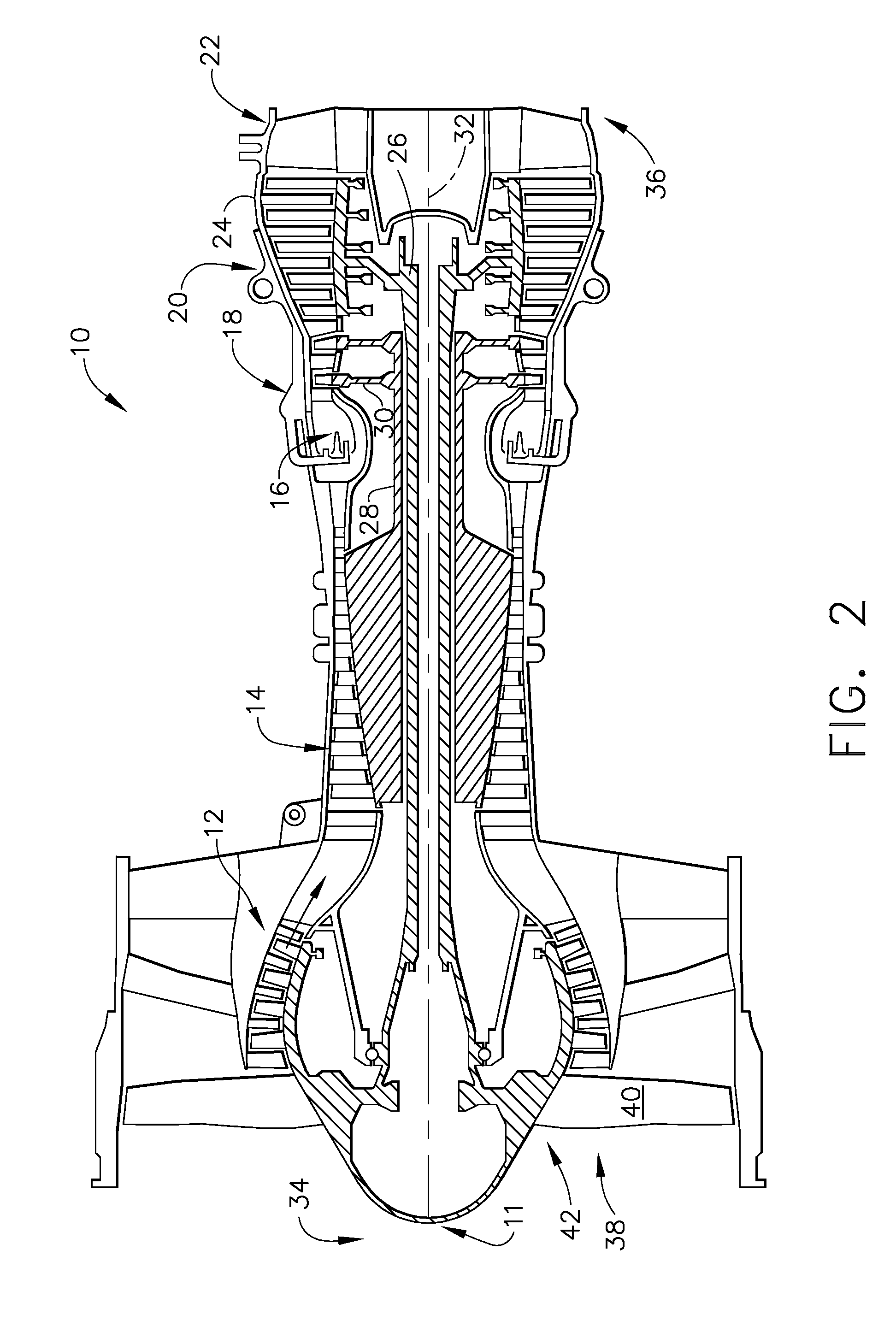
[0018]FIG. 2 is a schematic illustration of an exemplary gas turbine engine 10 that includes a fan assembly 11, a low-pressure compressor 12, a high-pressure compressor 14, and a combustor 16. Engine 10 also includes a high-pressure turbine (HPT) 18, a low-pressure turbine 20, an exhaust frame 22 and a casing 24. A first shaft 26 couples low-pressure compressor 12 to low-pressure turbine 20, and a second shaft 28 couples high-pressure compressor 14 to high-pressure turbine 18. Engine 10 has an axis of symmetry 32 extending from an upstream end 34 of engine 10 aft to a downstream end 36 of engine 10. Fan assembly 11 includes a fan 38, which includes at least one row of airfoil-shaped fan blades 40 attached to a hub member or disk 42.

[0019]In operation, air flows through low-pressure compressor 12 and compressed air is supplied to high-pressure compressor 14. Highly compressed air is delivered to combustor 16. Combustion gases from combustor 16 propel turbines 18 and 20. High pressure...


PUM

PropertyMeasurementUnit
vibrational frequencyaaaaaaaaaa
frictionaaaaaaaaaa
temperaturesaaaaaaaaaa

Abstract

A rotor blade assembly includes a shank, an airfoil that is formed integrally with the shank, and a removable platform coupled between said shank and said airfoil via a friction fit. A method of assembling a gas turbine engine rotor blade assembly that includes a removable platform, and a gas turbine engine rotor assembly including the removable platform are also described herein.

Description

BACKGROUND OF THE INVENTION[0001]This application relates generally to gas turbine engines and, more particularly, to gas turbine engine rotor blades and a method of fabricating a turbine rotor blade.[0002]FIG. 1 is a perspective view of a pair of known rotor blades that each include an airfoil 2, a platform 4, and a shank or dovetail 6. During fabrication, the known rotor blades are cast such that the platform is formed integrally with the airfoil and the shank. More specifically, the airfoil, the platform, and the shank are cast as a single unitary component.[0003]During operation, because the airfoil is exposed to higher temperatures than the dovetail, temperature gradients may develop at the interface between the airfoil and the platform, and / or between the shank and the platform. Over time, thermal strain generated by such temperature gradients may induce compressive thermal stresses to the platform. Over time, the increased operating temperature of the platform may cause platf...

Claims


Application Information

Patent Timeline
Patent Type & Authority Patents(United States)
IPC IPC(8): F01D5/18F01D5/30
CPCF01D5/147F01D5/16F01D5/326F01D11/008Y10T29/49337F05D2260/36F05D2240/81F05D2260/96
Inventor KEITH, SEAN ROBERTDANOWSKI, MICHAEL JOSEPHLEEKE, JR., LESLIE EUGENE
Owner GENERAL ELECTRIC CO
Features
  • R&D
  • Intellectual Property
  • Life Sciences
  • Materials
  • Tech Scout
  • Unparalleled Data Quality
  • Higher Quality Content
  • 60% Fewer Hallucinations
Learn More