Breakaway coupling for road-side signs

a technology of breakaway coupling and roadside signs, which is applied in the direction of roads, instruments, construction, etc., can solve the problems of further costs in time and money

Active Publication Date: 2011-07-19
DESIGNOVATIONS
View PDF15 Cites 23 Cited by
  • Summary
  • Abstract
  • Description
  • Claims
  • Application Information

AI Technical Summary

Benefits of technology

[0013]The primary objective of the present invention is to provide a new and unique coupling for use when installing a road-side sign, the coupling being uniquely configured to facilitate clean breakaway of the sign and sign post from the ground stake if the sign post is struck by an automobile.
[0014]Another important objective of the invention is to provide such a coupling that is low cost to manufacture and easy to use, without resulting in the need for additional expense beyond the simple coupling.
[0016]Another important objective of the invention is to prevent the anchor (i.e., ground stake) from disfiguring from an impact, by providing such a coupling that quickly and cleanly shears when the sign post is struck by an automobile, thereby protecting against damage to the anchor. With prior coupling, the inability to quickly and cleanly shear results in damage or disfigurement to the anchor, This necessitates removing the anchor and installing a new one which results in further costs in time and money with prior arrangements, and corresponding savings with the present invention.
[0024]In yet another alternate embodiment, the upper and lower sections of the breakaway coupling are formed with U-channel cross-sections having front sides for engaging back sides of a sign post bottom and a ground stake top, respectively, with approximately U-channel cross-sections. In this instance, the upper and lower sections are provided with clearance holes through the front sides of the U-channel cross-sections for fasteners to secure the coupling to the sign post and ground stake. The coupling may be further include bosses aligned with the clearance holes at the back sides of said U-channel cross-sections to provide additional strengths to support the fasteners.

Problems solved by technology

With prior coupling, the inability to quickly and cleanly shear results in damage or disfigurement to the anchor, This necessitates removing the anchor and installing a new one which results in further costs in time and money with prior arrangements, and corresponding savings with the present invention.

Method used


Image

  • Breakaway coupling for road-side signs
  • Breakaway coupling for road-side signs
  • Breakaway coupling for road-side signs

Examples


Embodiment Construction

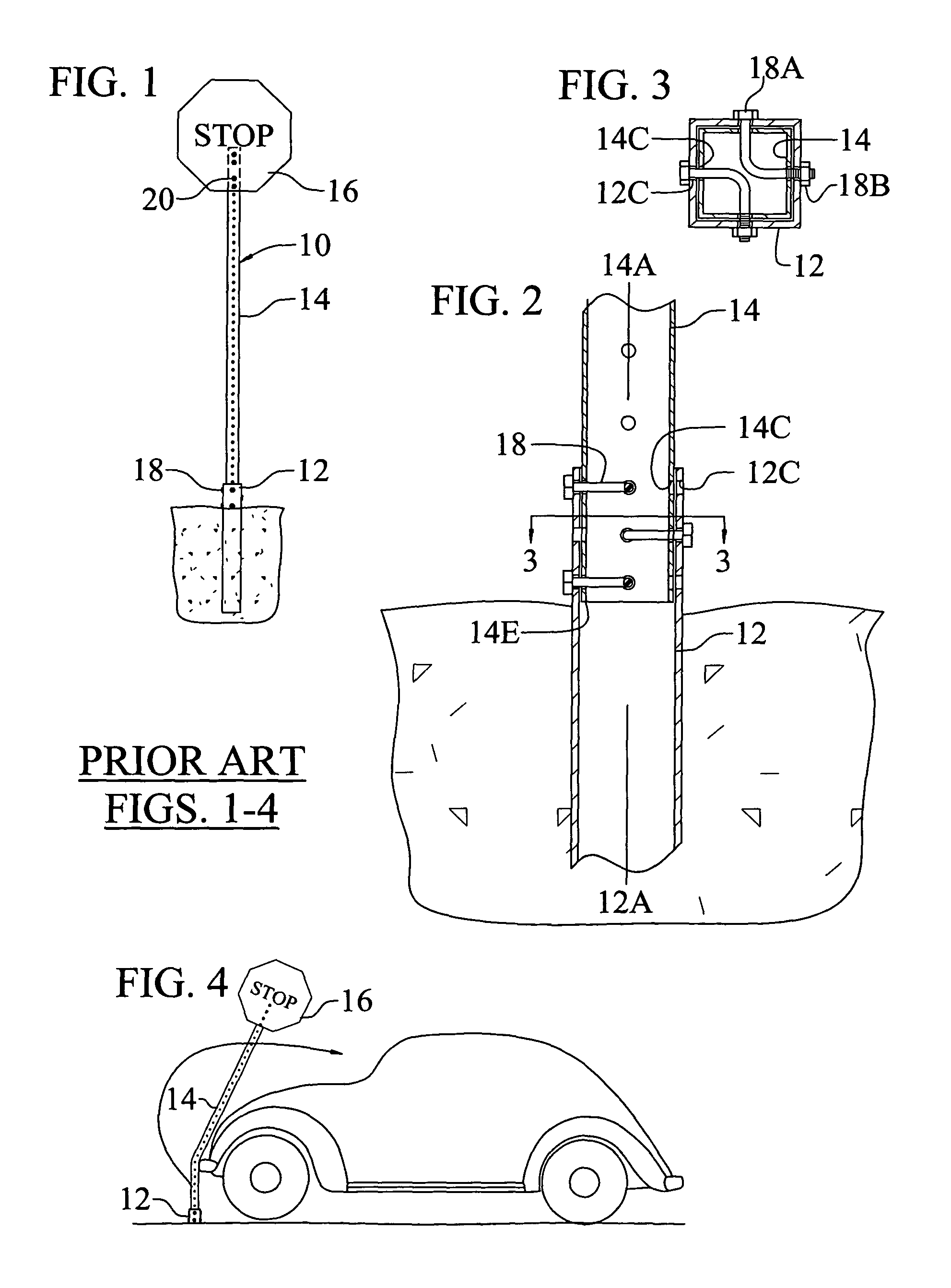
[0049]A stop sign 10 as conventionally installed is shown in FIG. 1 and includes a ground stake 12, a sign post 14, a stop sign 16, a set of angled fasteners 18 (FIG. 2), and a set of straight fasteners 20.

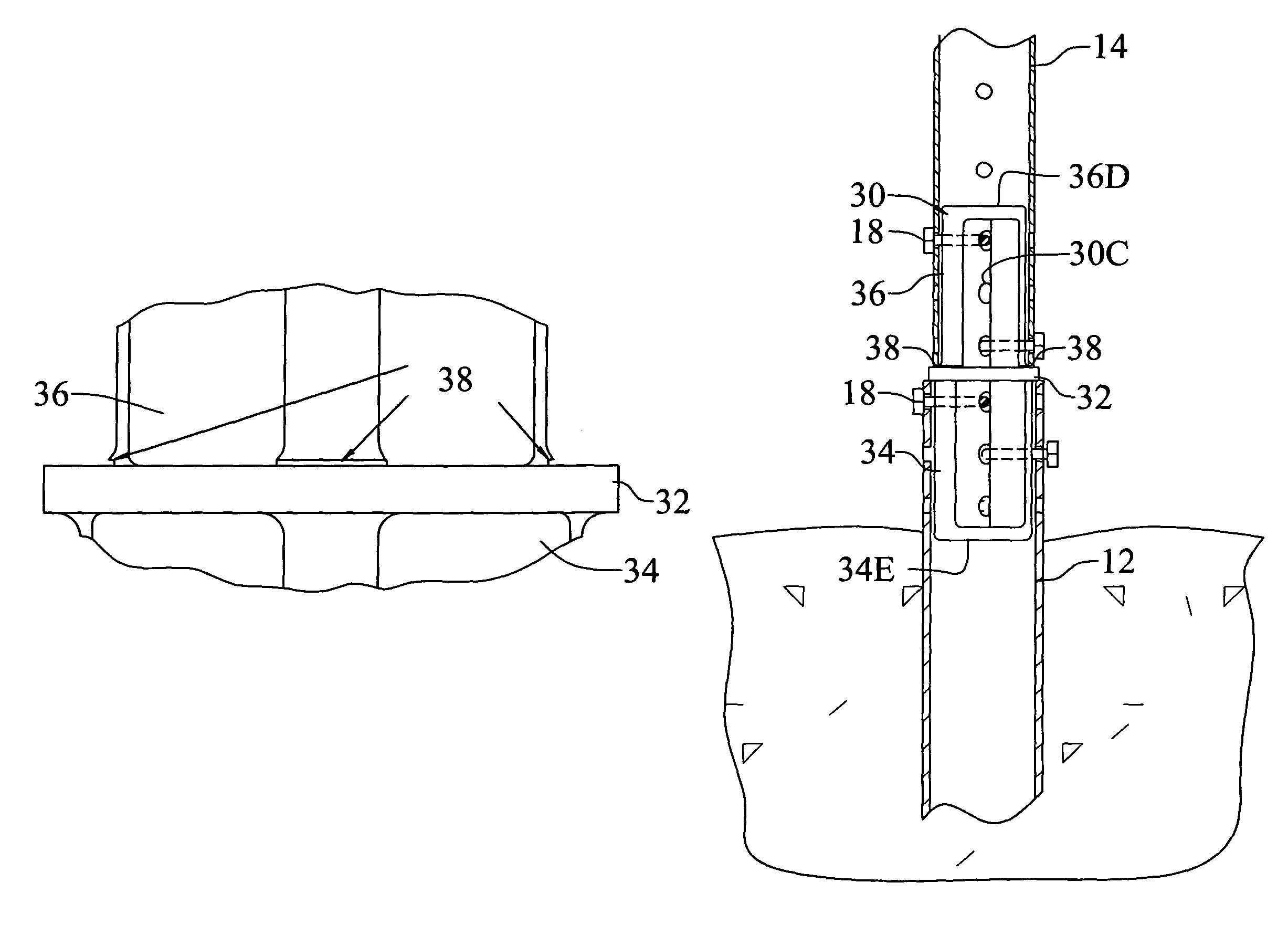
[0050]The ground stake 12 (or ground socket or anchor), is of hollow tubular steel construction, extending longitudinally along a center axis 12A through the hollow center of the tube, with an approximately square cross-section profile (see FIG. 3) perpendicular to the center axis thereof. The ground stake is installed into the ground in a vertical position, with the center axis vertical as shown, so that between approximately zero to four inches of the stake extends above the ground. The four side walls at the top of the ground stake are provided with sets of through holes 12C that are approximately centered in the width of each side, aligned in the sides at the same axial position on the stake, and therefore at the same height on the sides when the stake is installed into the gr...


PUM


Abstract

A breakaway coupling for use with a ground-installed road sign such as a stop sign typically located at the side of a road. The coupling interfaces between a conventional hollow ground stake and a hollow sign post. The coupling can be used with newly installed stop signs, as well as with currently installed stop signs, without modification to either the post of the ground stake. When the sign post is struck by an automobile, the coupling shears along a preformed score section generally aligned with the bottom of the post such that the post and sign break completely from the ground stake and are propelled away from the automobile.

Description

CROSS-REFERENCES TO RELATED APPLICATIONS[0001]This application claims priority to U.S. Provisional Patent Application Ser. No. 60 / 549,389 filed Mar. 2, 2004.INCORPORATION-BY-REFERENCE OF MATERIAL SUBMITTED ON A COMPACT DISC[0002]Not applicable.STATEMENT REGARDING FEDERALLY SPONSORED RESEARCH OR DEVELOPMENT[0003]Not applicable.BACKGROUND OF THE INVENTION[0004]1. Field of Invention[0005]The present invention relates to couplings to facilitate clean breakaway of road-side signs of the type carried on posts if the posts are struck by an automobile.[0006]2. Description of Prior Art[0007]Stop signs, as well as many other road side signs, are conventionally installed with a ground stake (or anchor), a square sign post, the sign, a set of angled fasteners, and a set of straight fasteners. The ground stake is hollow steel tube construction, with an approximately square (i.e., square or rectangular, hereinafter referred inclusively as square) cross-section profile, and is installed into the g...

Claims


Application Information

Patent Timeline
Patent Type & Authority Patents(United States)
IPC IPC(8): E01F9/018E01F15/00
CPCE01F9/0182E01F9/635Y10S256/05
Inventor ANDERSON, JIMTRAVIS, HARRY M
Owner DESIGNOVATIONS
Why Eureka
Try Eureka