Document presentation device including a movable part

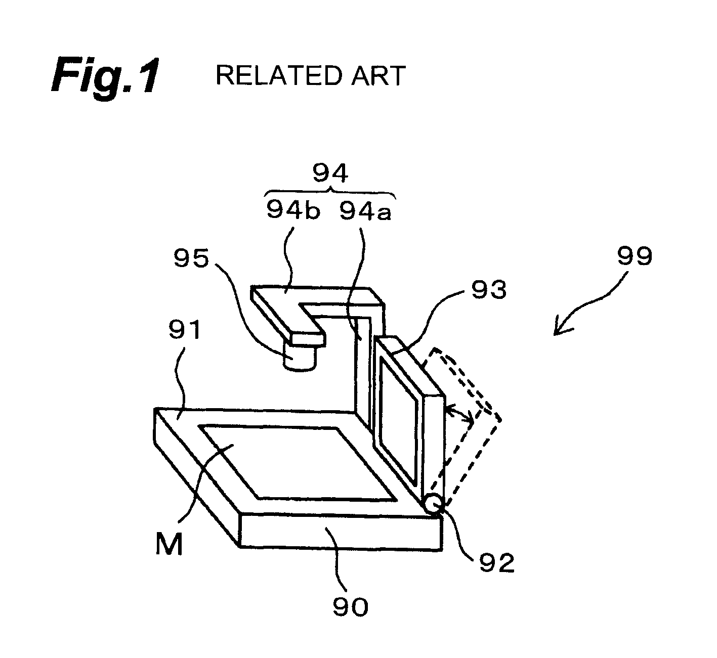
a document presentation device and movable part technology, applied in projectors, instruments, computing, etc., can solve the problems of document presentation devices b>99/b> being difficult to carry, document presentation devices being damaged, and affecting the preparation work, so as to reduce the preparation work

Inactive Publication Date: 2011-07-19
FUJI PHOTO OPTICAL CO LTD
View PDF14 Cites 8 Cited by
  • Summary
  • Abstract
  • Description
  • Claims
  • Application Information

AI Technical Summary

Benefits of technology

[0010]Therefore, it is an object of the present invention to provide a document presentation device in which each part can be compactly housed with respect to the main body without the occurrence of projections, and in which the device can be made smaller, requiring small storage space and small installation space.

Problems solved by technology

Also, when the document presentation device 99 is being carried, if the projections are positioned towards the side of the body of the person carrying the document presentation device 99, the projections impinge on the body of the person, making the document presentation device 99 difficult to carry.
On the other hand, if the projections are positioned on the opposite side of the document presentation device 99 to the body of the person, there is a danger that the projections will impact the corner of a desk or similar, causing damage to the document presentation device 99.

Method used


Image

  • Document presentation device including a movable part
  • Document presentation device including a movable part
  • Document presentation device including a movable part

Examples


first embodiment

(1) The First Embodiment

(1-1) Configuration of the First Embodiment

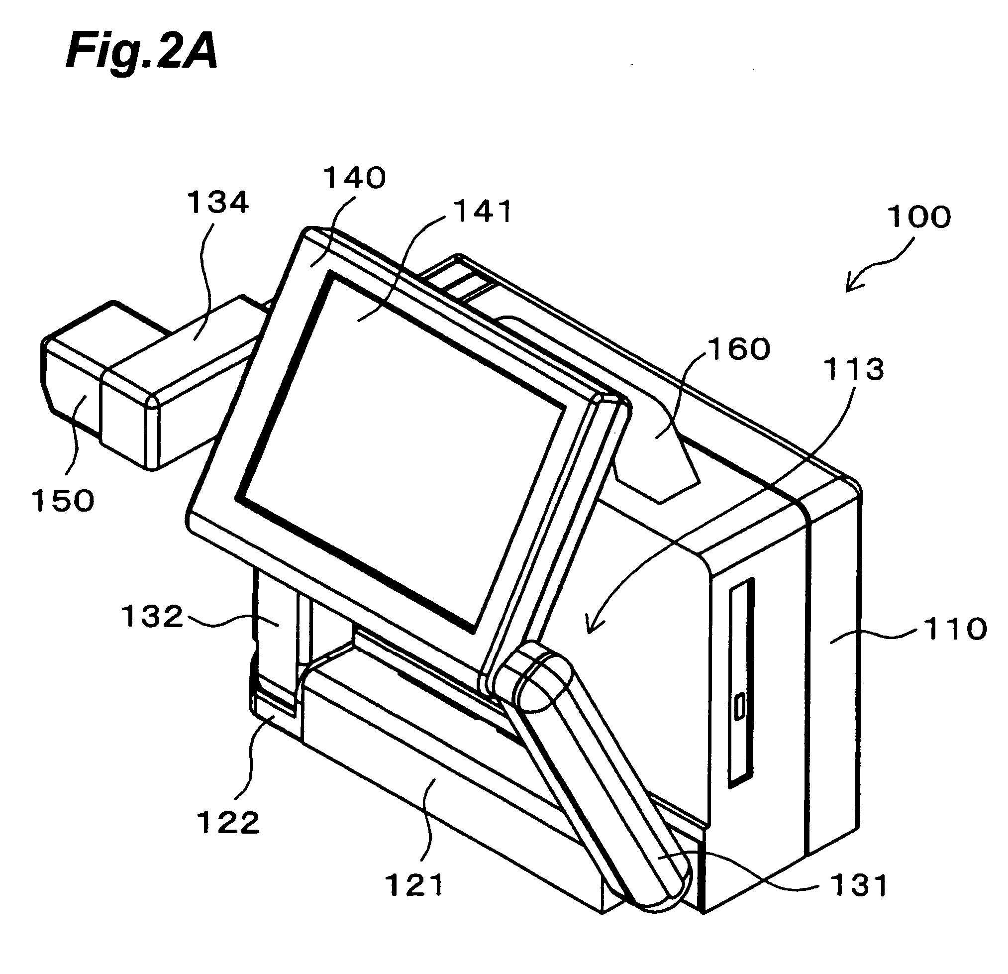
[0068]The following is an explanation of a first embodiment of the present invention with reference to the drawings. FIGS. 2A and 2B show the configuration of a document presentation device 100 according to a first embodiment of the present invention. FIG. 2A is an isometric view and FIG. 2B is a side view. FIG. 3 is an isometric view of the document presentation device 100 of FIG. 2A and 2B showing only a grip 160 on a main body 110 and a hinge mechanism 121FIG. 4 is a schematic side view of the document presentation device 100 of FIG. 2A and FIG. 2B showing a field of view α set by an imaging unit 150 and an A4 sized document within the field of view α. The document presentation device 100 includes a main body 110. As shown in FIG. 3, the main body 110 has length L1, width W1, and height H1. To reduce the storage and installation space of the document presentation device 100, the length L1, the width W1, and the he...

second embodiment

(2) The Second Embodiment

(2-1) Configuration of the Second Embodiment

[0086]In the following a document presentation device according to a second embodiment of the present invention is explained, using FIGS. 10, 11A, 11B, 12A, 12B, and 12C. As shown mainly in FIGS. 11A, 11B, 12A, 12B, and 12C, a document presentation device 300 according to the second embodiment includes the essential characteristics of the physical configuration of the document presentation device 100 according to the above first embodiment. FIG. 10 is a block diagram of the document presentation device 300 according to the second embodiment. Also, FIG. 11 A is an isometric view of the document presentation device 300 set in the attitude to be used. FIG. 11B is an isometric view seen from a different direction to that of FIG. 11A.

[0087]Also, FIG. 12A is an isometric view of the document presentation device 300 in the storage condition. FIG. 12B is a side view of the document presentation device 300 in the storage co...

third embodiment

(3) The Third Embodiment

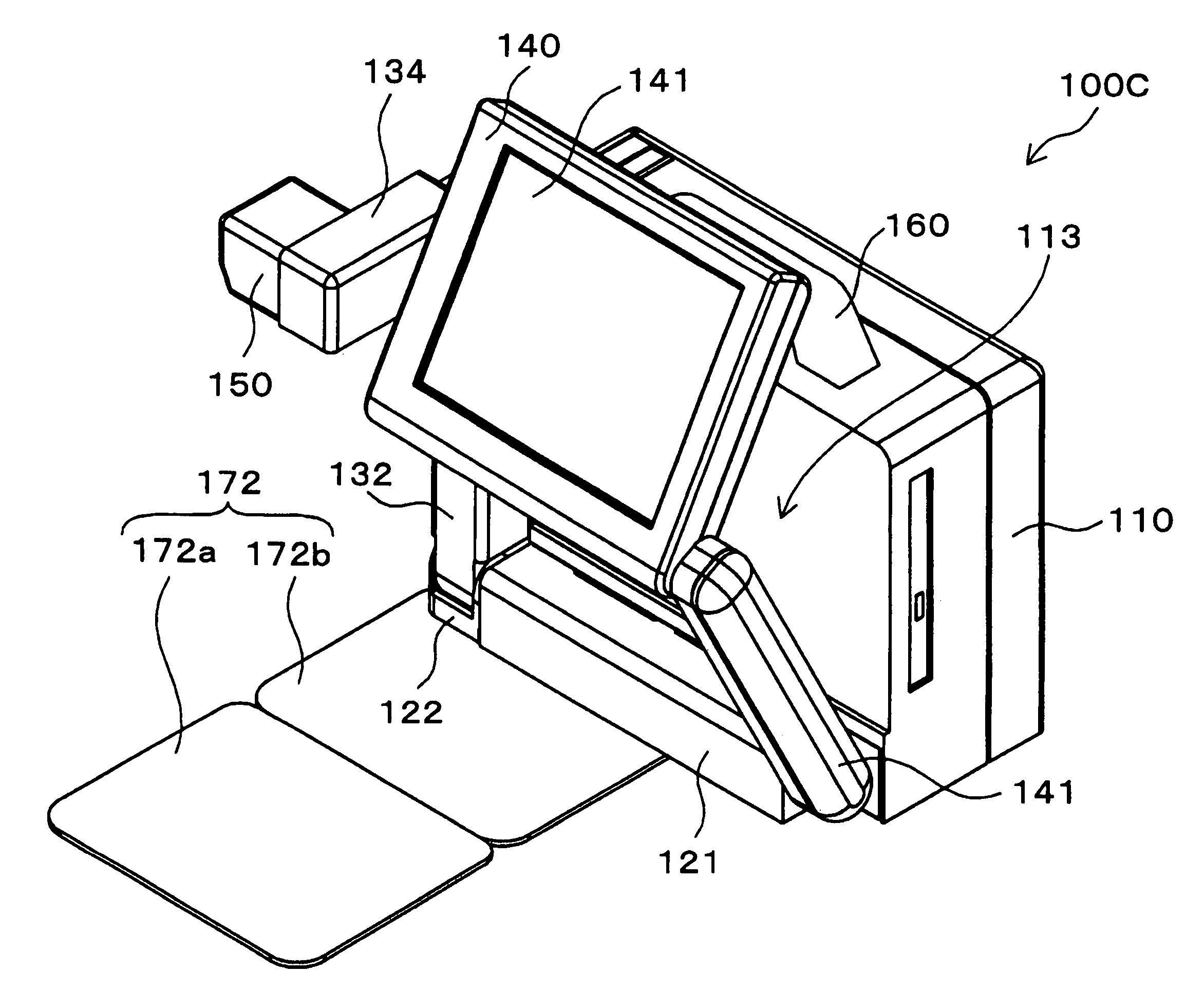
[0144]The following is an explanation of the document presentation device according to the third embodiment, using FIG. 18 and FIG. 19. FIG. 18 is an isometric view of a document presentation device 301 according to the present embodiment set in the attitude in which it can be used. The configuration of the document presentation device 301 is that of the document presentation device 300 excluding the first rotatable body 17A, the second rotatable body 17B, and the projector unit 17, and including a first rotatable body 17C, a rotatable body support unit 18B, a projector unit 177, an opening and closing unit 19, and a cover 191 that houses the opening and closing unit 19. Also, FIG. 19 shows the schematic configuration near the first rotatable body 17C, the rotatable body support unit 18B, the projector unit 177, and the opening and closing unit 19. FIG. 18 and FIG. 19 show the situation when the cover 191 is removed.

[0145]The first rotatable body 17C is a cyl...


PUM


Abstract

A document presentation device comprising an imaging unit that takes images of documents and a display unit that displays the images of documents taken by the imaging unit.

Description

BACKGROUND OF THE INVENTION[0001]1. Field of the Invention[0002]The present invention relates to a document presentation device for presenting documents at for example meetings or similar. More particularly the present invention relates to a document presentation device in which images of materials such as original documents are taken by an imaging unit and the image is displayed on a screen, display, or similar, and in particular to a document presentation device with an improved method of housing each part.[0003]2. Related Background Art[0004]In recent years document presentation devices have been used instead of overhead projectors (OHP) for projecting images of documents onto a screen, so that the audience at a presentation can refer to the projected image while the contents of the document is being explained.[0005]For example, the document presentation device 99 shown in FIG. 1 includes a document base 90 forming the base of the device. The document base 90 includes a document ...

Claims


Application Information

Patent Timeline
Patent Type & Authority Patents(United States)
IPC IPC(8): G03B21/14G03B21/22G06F17/00G06F3/041
CPCH04N1/00129H04N1/00347H04N1/00392H04N1/00411H04N1/00413H04N1/04H04N1/19594H04N1/0035H04N1/195H04N2201/0075H04N2201/0081H04N2201/0089H04N2201/0096H04N2201/043H04N2201/0436H04N2201/045
Inventor ISHIKAWA, HIROKAZUYOKOYAMA, JUNICHINAGASHIMA, TAKASHIHAMANA, AKINORI
Owner FUJI PHOTO OPTICAL CO LTD
Why Eureka
Try Eureka