Screw placement guide

a screw and guide technology, applied in the field of screw placement guides, can solve the problems of premature screw pulling out, fracture of the bone to which the screw is attached, and uneven placement of the screw, etc., and achieve the effect of minimally invasive surgery

Active Publication Date: 2011-07-19
DEPUY SPINE INC (US)
View PDF16 Cites 40 Cited by
  • Summary
  • Abstract
  • Description
  • Claims
  • Application Information

AI Technical Summary

Benefits of technology

[0009]The present invention provides a system, device and method for placing rod receiving screws for implantation in spinal fixation surgery to ensure that rod receiving screws are properly placed so that, as a result of ensuring correct screw placement, surgeons will not need to apply undue force to orient the rod receiving screws to receive the spinal fixation rod to be implanted. The system, device and method of the invention can be advantageously adapted to be particularly useful in minimally invasive surgery. In a first aspect of the invention, a screw placement guide tool for use in minimally invasive surgery is provided having a proximal handle portion, an extension member extending distally from the handle portion, and an alignment element connected transversely to a distal portion of the extension member and having a screw placement guide located thereon. In this aspect of the invention, the tool is configured so that a surgeon may operate the tool using the handle portion external to a patient's body to align the alignment element with implanted screws so that the screw placement guide indicates a desired position for implantation of an additional screw.

Problems solved by technology

Such loads can result in improper alignment of the vertebrae, premature screw pull out, and fracture of the bone to which the screw is attached.

Method used


Image

  • Screw placement guide
  • Screw placement guide
  • Screw placement guide

Examples


Embodiment Construction

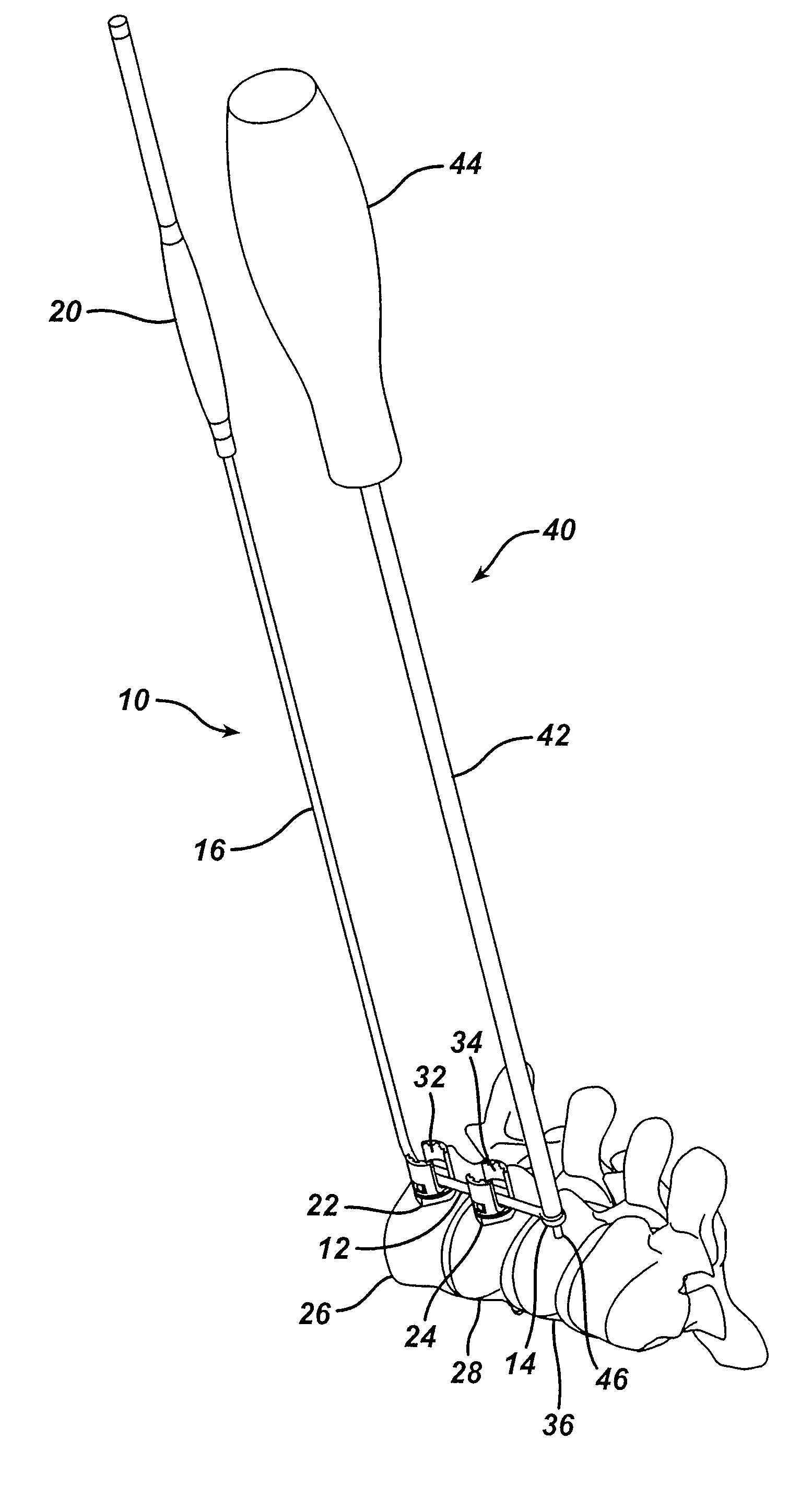
[0020]The present invention provides a system, device and method for placing rod receiving screws for implantation in spinal fixation surgery. The system, device and method of the invention can be configured to be particularly useful in minimally invasive surgery to ensure that rod receiving screws are properly placed so that, as a result of ensuring correct screw placement, surgeons will not need to apply undue force to orient the rod receiving screws to receive the spinal fixation rod to be implanted.

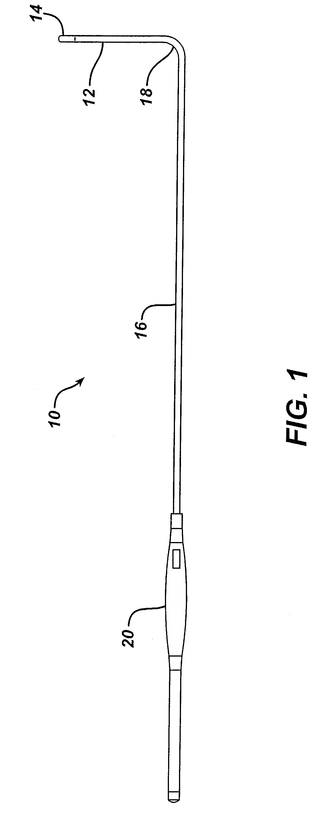
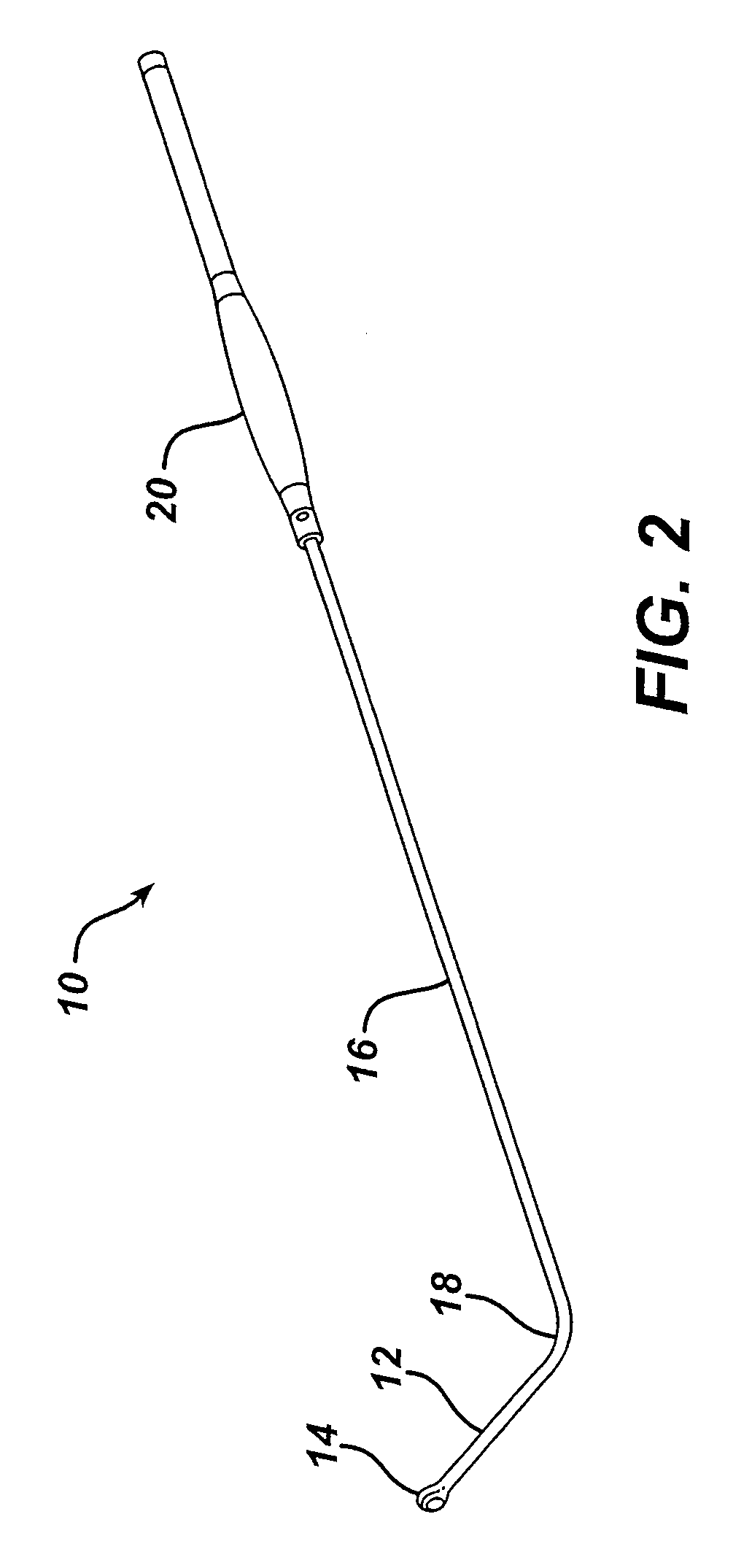
[0021]A screw placement guide tool 10 of the invention is illustrated in side and perspective views in FIGS. 1 and 2, respectively. Guide tool 10 includes an elongate alignment element 12 having a placement guide 14 disposed thereon. Placement guide 14 is shown as a closed loop, however, any guide or directional marker useful for placing a screw may be used. For example, placement guide 14 could simply be a blunt end against which a rod receiving screw could be aligned for placement i...


PUM


Abstract

A screw placement guide tool for use in minimally invasive surgery has a proximal handle portion, an extension member extending distally from the handle portion, and an alignment element connected transversely to a distal portion of the extension member and having a screw placement guide located thereon. In this aspect of the invention, the tool is configured so that a surgeon may operate the tool using the handle portion external to a patient's body to align the alignment element with implanted screws so that the screw placement guide indicates a desired position for implantation of an additional screw. Systems and methods for placing a rod receiving screw are also provided.

Description

RELATED APPLICATIONS[0001]This application is a divisional application of U.S. patent application Ser. No. 10 / 256,636, filed on Sep. 27, 2002 and entitled “Screw Placement Guide,” and this application further claims priority to provisional application U.S. Ser. No. 60 / 400,912, filed Aug. 2, 2002, each of which are expressly incorporated by reference herein.FIELD OF THE INVENTION[0002]The present invention relates to devices and methods for placing a screw to be inserted in a patient's vertebrae during spinal fixation surgery.BACKGROUND OF THE INVENTION[0003]The use of spinal fixation instrumentation to align and / or fix a desired relationship between adjacent vertebral bodies is well established. Such instrumentation typically includes a spinal fixation element, such as a relatively rigid fixation rod, that is coupled to adjacent vertebrae by attaching the element to screws which have been inserted into the patient's vertebrae or to spinal hooks which can be placed into a vertebral a...

Claims


Application Information

Patent Timeline
Patent Type & Authority Patents(United States)
IPC IPC(8): A61B17/58A61F2/00A61B17/00A61B17/17
CPCA61B17/1757A61B2017/00238
Inventor NEWTON, PETERGRACIA, MARKVARIEUR, MICHAEL S.BREECH, CARRIE A.
Owner DEPUY SPINE INC (US)
Why Eureka
Try Eureka