
Multi-reflecting time-of-flight mass analyser and a time-of-flight mass spectrometer including the mass analyser

a mass analyser and multi-reflecting technology, applied in the field of mass spectrometry, can solve the problem that the adjustment is not possible using known systems with lenses, and achieve the effects of improving overall mass resolution, reducing ion loss from the analyser, and relatively stable ion motion in the transverse direction

Active Publication Date: 2011-07-19
SHIMADZU CORP
View PDF13 Cites 39 Cited by
  • Summary
  • Abstract
  • Description
  • Claims
  • Application Information

AI Technical Summary

Benefits of technology

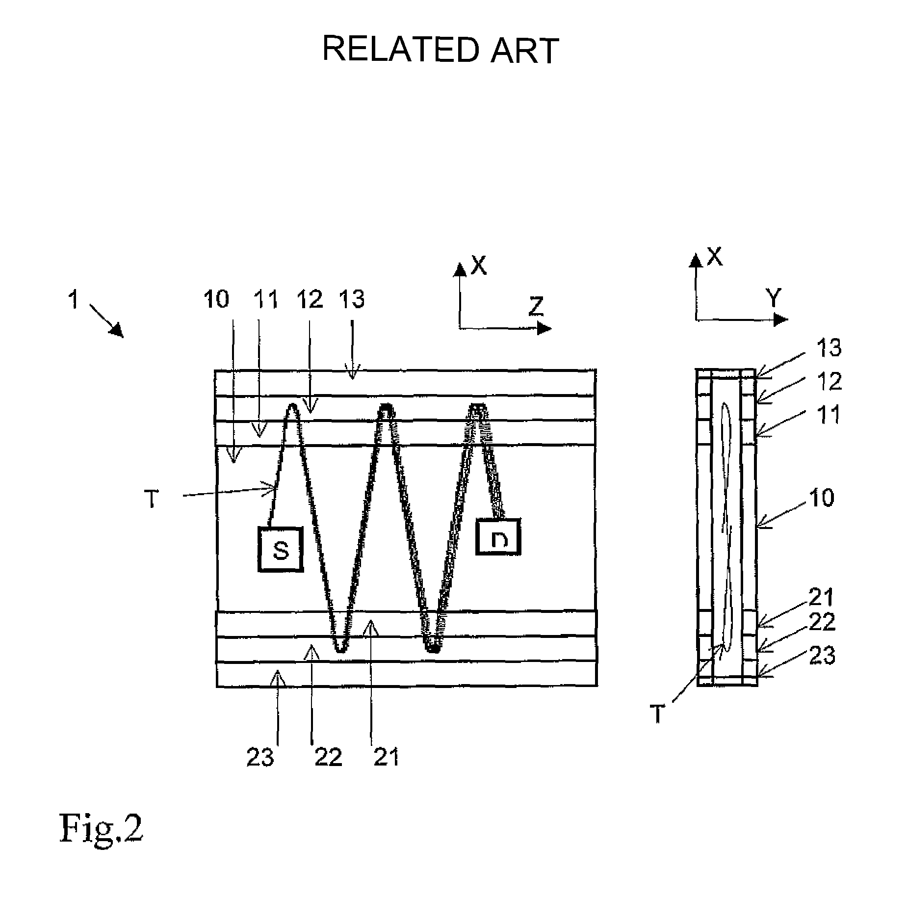
[0009]In an embodiment of the invention, the TOF mass analyser may be used as a delay line which may be incorporated in the flight path of virtually any existing TOF mass spectrometer with a view to improving overall mass resolution by virtue of the extended flight time created by the delay line. With the folded path configuration of the invention there is no limitation on the range of mass-to-charge ratio that can be accommodated by the analyser, and the need to manipulate the ion trajectory using pulsed voltage is avoided. Furthermore, ion motion in the transverse direction is relatively stable. This, in conjunction with the use of gridless ion mirrors helps to reduce ion loss from the analyser. The extended flight time gives improved resolving power of mass analysis and, in preferred embodiments, the number of reflections can be adjusted using electrostatically controllable deflector means to control an angle, relative to the flight direction, at which ions are directed onto the folded ion path. Such adjustment is not possible using known systems having lenses.
[0010]The invention introduces a completely novel feature in the design of TOF systems—that is, energy focussing in the drift direction, orthogonal to the flight direction. Prior to this, TOF systems were built in such a way as to minimise beam spread in the drift direction by accelerating beams to high energy in order to reduce overall angular spread or by using lenses to refocus the beam. In addition to the provision of ion mirrors in the flight direction the present invention proposes uses of an ion mirror in the drift direction (orthogonal to the flight direction) and may be used to produce an energy focus in the final position at the detector simultaneously with respect to both the flight and drift directions. Due to the isochronous property of the system beam width in drift direction during flight is irrelevant though, preferably the beam should not be wider than the detector when it is detected. This has the additional advantage of reducing the influence of space charge because most of the time ion packets travel elongated in drift direction.

Problems solved by technology

Such adjustment is not possible using known systems having lenses.

Method used


Image

  • Multi-reflecting time-of-flight mass analyser and a time-of-flight mass spectrometer including the mass analyser
  • Multi-reflecting time-of-flight mass analyser and a time-of-flight mass spectrometer including the mass analyser
  • Multi-reflecting time-of-flight mass analyser and a time-of-flight mass spectrometer including the mass analyser

Examples


Embodiment Construction

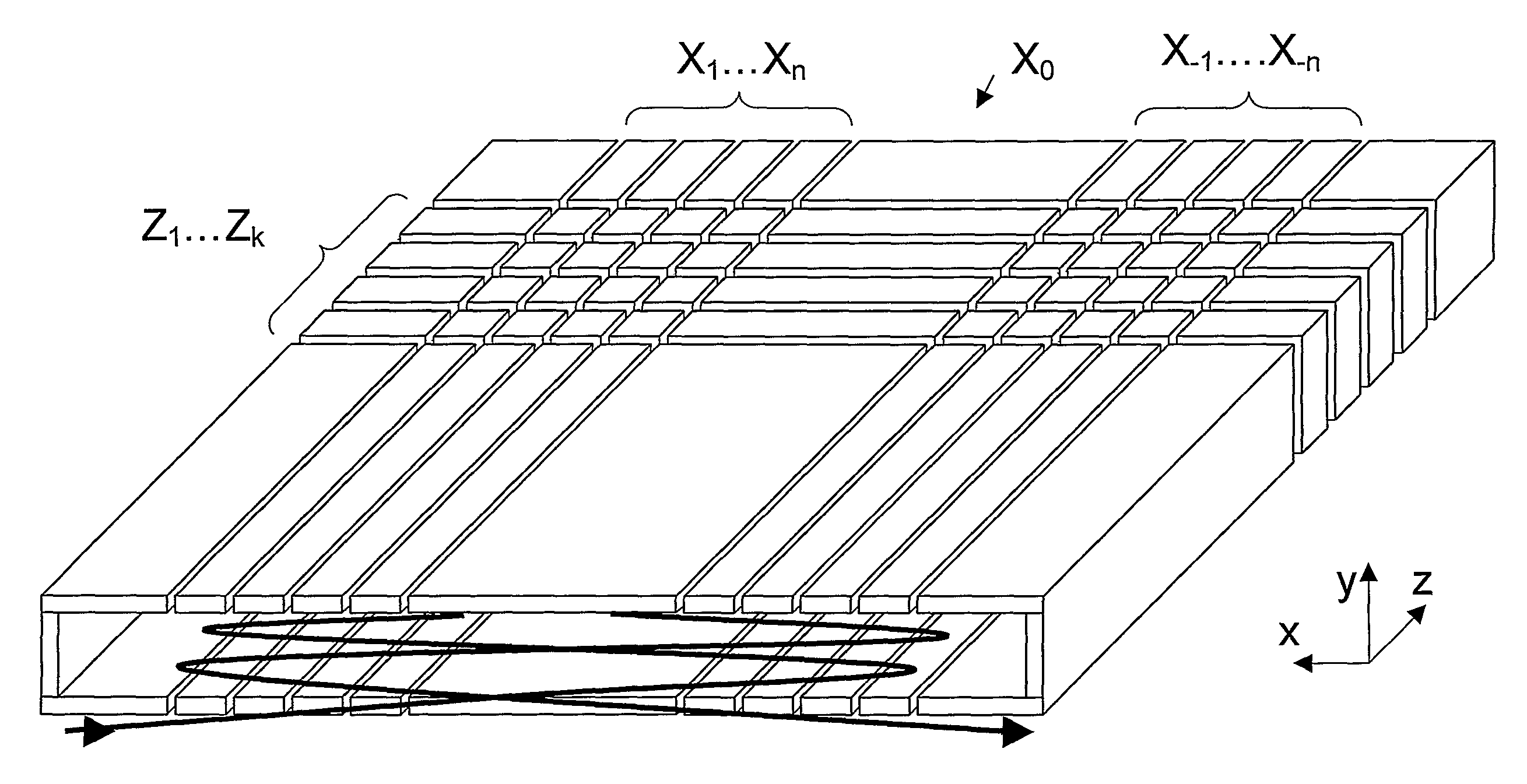
[0026]FIG. 4 shows a 3D view of the novel multi-reflecting 2D isochronous TOF mass analyser according to a preferred embodiment of the invention. The 2DTOF analyser consists of a set of metal plate electrodes positioned in two parallel planes orthogonal to the Y axis. Electrodes in the upper and lower planes are symmetrical and have the same applied voltages. The plate electrodes are arranged in lines X1, X2, . . . , Xn and X−1, X−2, . . . , X−n parallel to the Z axis. These electrodes form two gridless electrostatic ion mirrors for reflecting ions in the flight direction X. Each X line electrode is subdivided into a number of segments so as to create lines Z1, Z2, . . . , Zk of electrodes which extend parallel to X axis. These lines of electrodes are used to form an ion mirror in the drift direction Z. FIG. 5 shows a schematic representation of the 2DTOF system in 3 orthogonal views with a typical ion trajectory (T) through the system. 2DTOF analyser 3 comprises an ion source S and...


PUM


Abstract

A multi-reflecting TOF mass analyser has two parallel, gridless ion mirrors each having an elongated structure in a drift direction (Z). These ion mirrors provide a folded ion path formed by multiple reflections of ions in a flight direction (X), orthogonal to the drift direction (Z). The analyser also has a further gridless ion mirror for reflecting ions in the drift direction (Z). In operation ions are spatially separated according to mass-to-charge ratio due to their different flight times along the folded ion path and ions having substantially the same mass-to-charge ratio are subjected to energy focusing with respect to the flight and drift directions.

Description

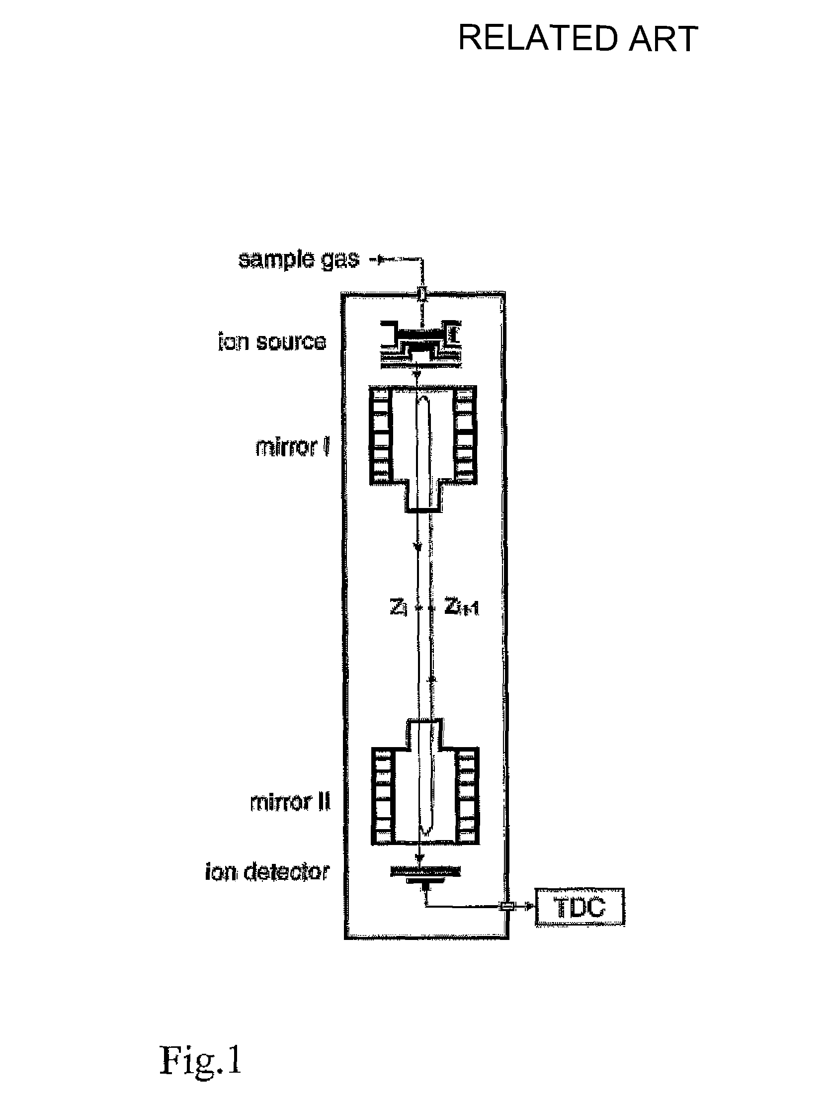
FIELD OF THE INVENTION[0001]This invention relates to the field of mass spectrometry, particularly time-of-flight mass spectrometry. In particular, it relates to a TOF mass analyser having increased flight path due to multiple reflections.BACKGROUND[0002]The time-of-flight (TOF) method of mass spectrometry is based on a measurement of the time it takes for ions to fly from an ion source to a detector along the same path. The ion source simultaneously produces pulses of ions having different mass-to-charge ratios but of the same average energy. Thus, due to the laws of motion in an electrostatic field the flight time for ions having different mass-to-charge ratios (m / e) is inversely proportional to the square root of m / e. Ions arriving at the detector produce pulses of current which are measured by a control system and presented in the form of a spectrum. The mass-to-charge ratio of ions under investigation can be derived by comparing the position of their peak with respect to peaks ...

Claims


Application Information

Patent Timeline
Patent Type & Authority Patents(United States)
IPC IPC(8): H01J49/40
CPCH01J49/406
Inventor SUDAKOV, MICHAEL
Owner SHIMADZU CORP
Learn More