Device for transferring ions from high to low pressure atmosphere, system and use

a technology of transferring ions and atmosphere, applied in the field of tubelike devices, can solve the problems of further ion loss, reducing the ion yield at the analyser, and disadvantageous embodiments known from the prior art, and achieve the effect of reducing ion loss and reducing ion loss

Active Publication Date: 2016-07-19
MAX PLANCK GESELLSCHAFT ZUR FOERDERUNG DER WISSENSCHAFTEN EV +1
View PDF11 Cites 0 Cited by
  • Summary
  • Abstract
  • Description
  • Claims
  • Application Information

AI Technical Summary

Benefits of technology

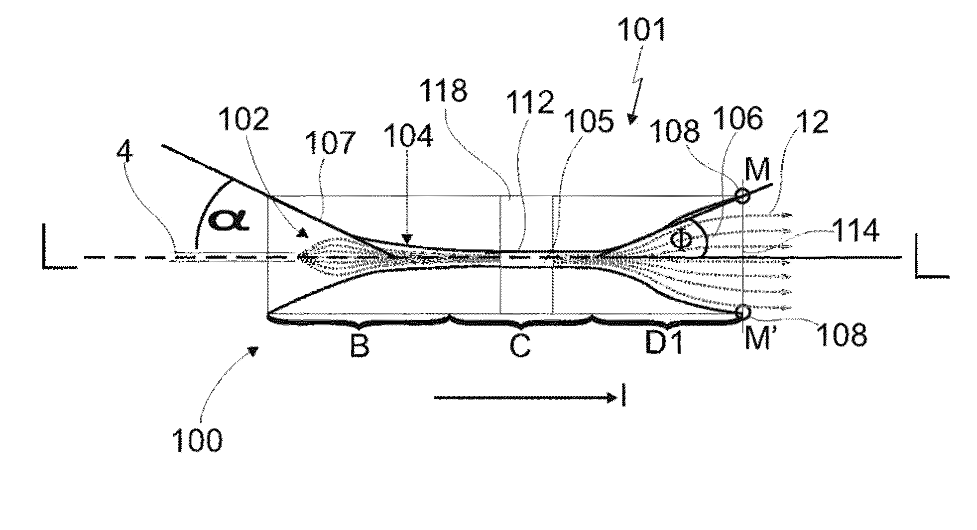
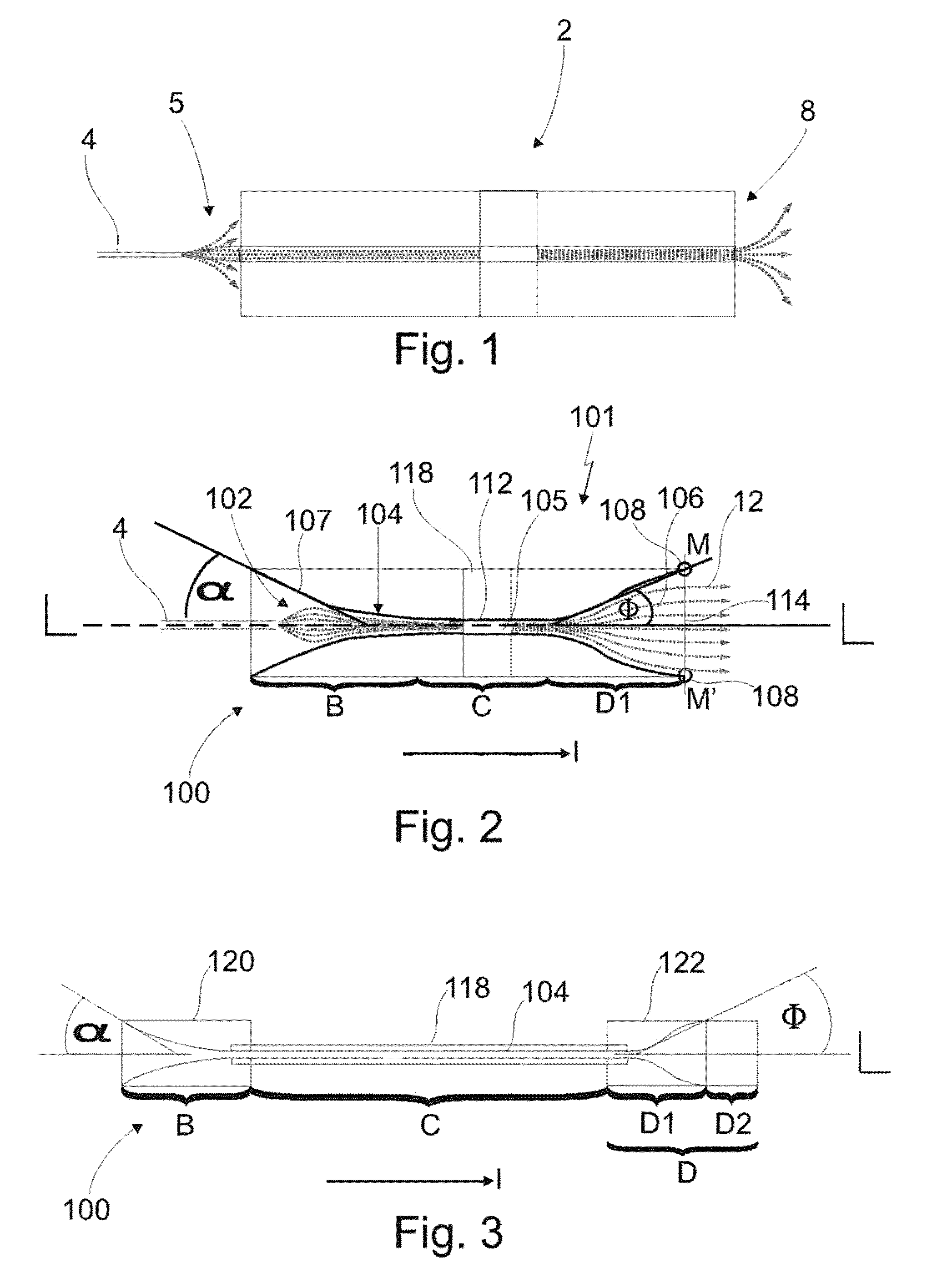
[0064]Furthermore, it is conceivable that the middle portion is not restricted to a regular cylindrical shape. In further embodiments, the middle portion may have alternative cross-sections like ellipsoidal, squared or polygonal in general. Moreover, the cross-section of the middle portion, which is perpendicular arranged with respect to the longitudinal axis, may vary in longitudinal direction of the device according to the invention. This is advantageous for the ion transfer through the device in order to reduce ion losses.
[0065]Moreover, in a simple embodiment, the middle portion is linear. However, in dependence of the ions it is also conceivable that the middle portion is provided in a curved manner providing at least one change in direction with respect to the longitudinal direction. This curvature may be concave and / or convex. In dependence of the radius of the curvature, a pre-selection of the ions transferred through the middle portion is provided because ions with a low molecular mass follow the curvature whereas ions with higher molecular masses collide with inner wall regions. Optionally, additional ion optics are used for an improved guidance of the ions in a curved middle portion in order to reduce ion losses.

Problems solved by technology

The embodiments known from the prior art are disadvantageous because the gaseous ion cloud emerging from the ion generation source expands due to space charge effects.
Furthermore the geometric form of the capillaries known from the prior art causes perturbations in the gas flow at the capillary entrance, especially at the edges like for example stall or vortex flow, inducing further ion losses and reducing the ion yield at the analyser.

Method used


Image

  • Device for transferring ions from high to low pressure atmosphere, system and use
  • Device for transferring ions from high to low pressure atmosphere, system and use
  • Device for transferring ions from high to low pressure atmosphere, system and use

Examples


example

[0095]In first experiments the transmission of an API with a funnel-like inlet portion was compared with its conventional counterpart. An ion source 4 with a device 2, 100 was constructed, wherein the device could be exchanged without altering the geometry, realizing comparable measurements.

[0096]Experiments with capillary 2 and device 100 were carried out using a nanoelectrospray ion source made of a pulled silica capillary emitter of 25 μm inner diameter, producing net currents of 20-40 nA from a 10-mmol / mL rhodamine 6G solution flowing at 20 μL / h.

[0097]A device 2 with a diameter of 1 mm, a short length of 70 mm was pre-heated to 180° C. In the vacuum chamber, pumped with a rotary pump with 16 m3 / h, a pressure of 20 mbar was adjusted. In this chamber the transmitted current Itrans was measured on a target 140 mounted 2 cm downstream of the device 2. The loss current Icap was detected on the capillary 2. The total current emitted from the ion source Itot is equal to Itrans+Icap.

[00...


PUM


Abstract

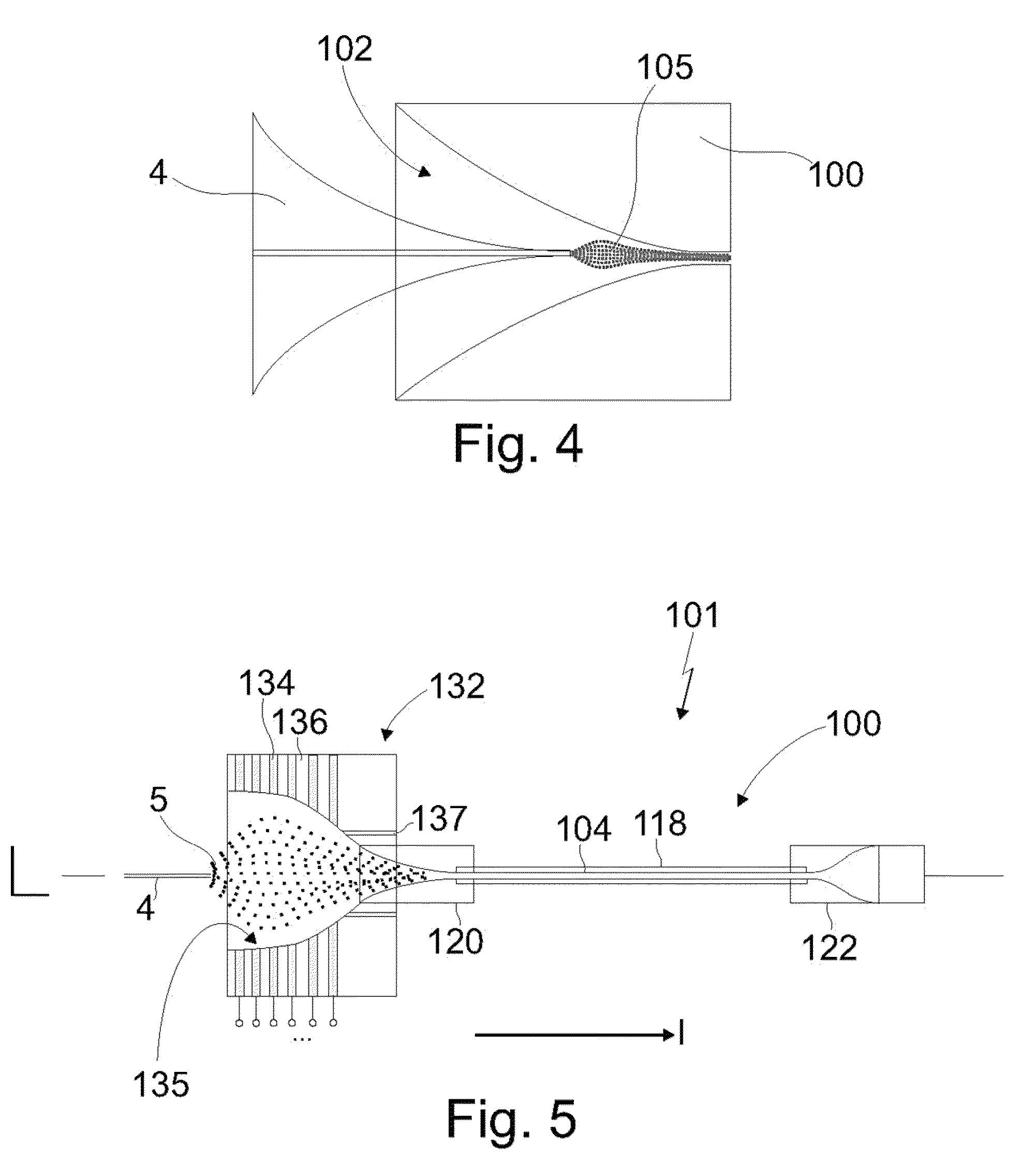
Tube-like device (100) for transferring ions generated by means of ion generation source (4) comprising a cylindrical middle portion (104) and an inlet portion (102) for introduction of the ions in at least one ion cloud into the cylindrical middle portion (104), wherein a flow direction of the ions is along a longitudinal axis (L) of the tube-like device (100), wherein the inlet portion (102) is formed tapering funnel-like towards the cylindrical middle portion (104).

Description

CROSS-REFERENCE TO RELATED APPLICATIONS[0001]This application is a U.S. National Stage Application filed under 35 U.S.C. §371 of International Application No. PCT / EP2013 / 053471, filed Feb. 21, 2013, which claims the benefit of European Application No. 12 156 326.6, filed Feb. 21, 2012, and U.S. Provisional Patent Application No. 61 / 647,940, filed May 16, 2012. All of these applications are hereby incorporated by reference in their entireties.BACKGROUND OF THE INVENTION[0002]The present invention concerns a tube-like device for transferring ions generated by means of an ion generation source, comprising a cylindrical middle portion and an inlet portion to introduce ions in at least one ion cloud into the cylindrical middle portion, wherein at least one flow direction of the ions is along a longitudinal axis of the tube-like device.[0003]In analytical chemistry, to determine the composition of unknown analytes, frequently mass spectrometry is used. The specimen composition to be teste...

Claims


Application Information

Patent Timeline
Patent Type & Authority Patents(United States)
IPC IPC(8): H01J49/04
CPCH01J49/0404H01J49/0445H01J49/0459
Inventor RAUSCHENBACH, STEPHANPAULY, MATTHIASRINKE, GORDONVOGELGESANG, RALFKERN, KLAUSREISS, JULIUSSESTERHENN, JOERNSROKA, MARIO
Owner MAX PLANCK GESELLSCHAFT ZUR FOERDERUNG DER WISSENSCHAFTEN EV
Why Eureka
Try Eureka