Flexible display device

a flexible display and display device technology, applied in the direction of identification means, semiconductor/solid-state device details, instruments, etc., can solve the problems of reducing affecting the operation of the flexible display device, and affecting so as to improve the useful life of the display devi

Inactive Publication Date: 2011-07-19
SIGNIFY HLDG BV
View PDF11 Cites 4 Cited by
  • Summary
  • Abstract
  • Description
  • Claims
  • Application Information

AI Technical Summary

Benefits of technology

[0007]By providing a flexible thermo regulating layer to the substrate, heat may be dissipated from the substrate and light source(s) and other possible display components, which allows for consistent operation and increased endurance of the display device. Further, using a flexible thermo regulating layer allows the display device to maintain its overall flexible nature.
[0008]In one embodiment, the thermo regulating layer is made of a non-stretchable material, such as Neoprene. The non-stretchable layer offers physical strength protection against damage to the flexible display substrate. For instance, it allows for “stretch protection” of a non-stretchable display substrate, which is especially advantageous in case the display device is attached to a stretchable material, such as the fabric of a garment.
[0010]In one embodiment, a breathable fabric layer is provided on the opposite side of the thermo regulating layer compared to the side facing the flexible substrate. The breathable fabric layer allows heat to be transferred out from the flexible display device, while still providing an outer surface with a fabric feel, which may be advantageous in case the flexible display device is incorporated in a textile product such as a garment. The breathable fabric layer may also be waterproof, to protect the display device from moisture.

Problems solved by technology

However, during operation of a flexible display device, the light sources and associated components and elements may generate considerable heat.
This in turn may hamper the operation of the flexible display device, since the output of the light sources usually depends on temperature.
It may also reduce the useful life of the display, since elevated temperatures usually accelerates the degradation of the electrical components of the display.

Method used


Image

  • Flexible display device
  • Flexible display device

Examples


Embodiment Construction

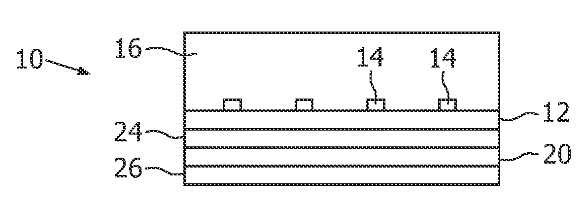
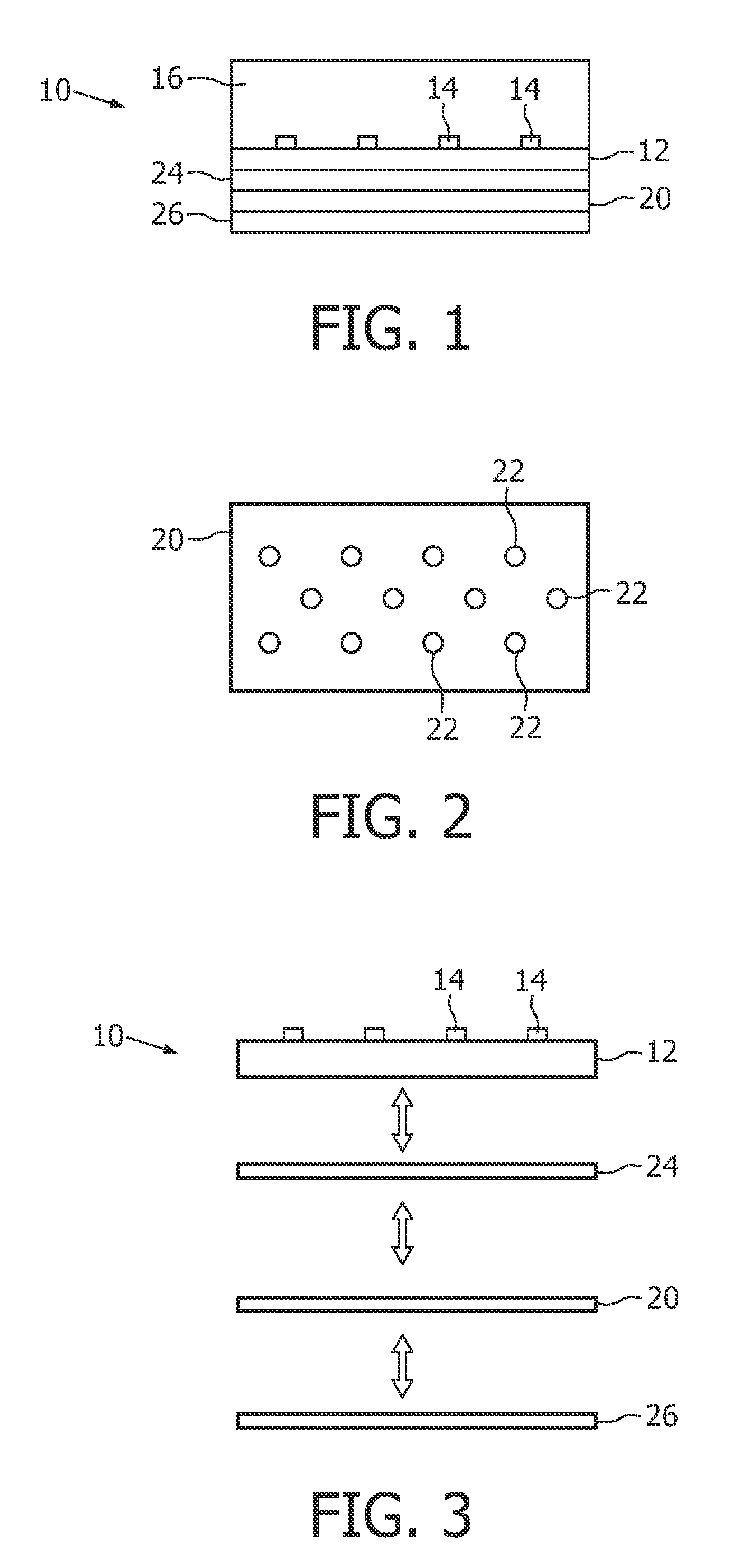
[0019]FIG. 1 is a cross-sectional side view of a flexible display device 10 according to an embodiment of the invention. The flexible display device 10 comprises a flexible substrate 12, which for example can be made of plastics or fabrics, and a plurality of discrete light sources 14, preferably light emitting diodes (LEDs). The flexible display device 10 may optionally comprise a diffusing element 16 arranged to receive and diffuse light emitted from the light sources 14 of the flexible display device 10. An example of such a flexible display device with diffusing element is for example disclosed in the above-mentioned document WO2004 / 100111.

[0020]According to the present invention, the flexible display device 10 further comprises a flexible thermo regulating layer 20 provided on the opposite side of the flexible substrate 12 compared to the side with the light sources 14. The flexible thermo regulating layer 20 is preferably made of a non-stretchable material, preferably Neoprene...


PUM


Abstract

The present invention relates to a flexible display device (10) comprising a flexible substrate (12) having at least one light source (14) mounted thereon. The flexible display device is characterized by a flexible thermo regulating layer (20) provided on the opposite side of the substrate compared to the side with the at least one light source for dissipating heat from the remaining display device. This allows for stable operation and increased endurance of the display device. The present invention also relates to a textile product comprising such a flexible display device, and a method for the manufacturing of such a flexible display device.

Description

TECHNICAL FIELD OF THE INVENTION[0001]The present invention relates to a flexible display device comprising a flexible substrate having at least one light source mounted thereon. The present invention also relates to a textile product comprising such a flexible display device, and a method for the manufacturing of such a flexible display device.BACKGROUND OF THE INVENTION[0002]An example of such a flexible display device is disclosed in the document WO2004 / 100111. The flexible display device in WO2004 / 100111 comprises a fabric support with woven threads including electrically conductive threads, and discrete electro luminescent sources soldered to the conductive threads. The flexible display device can be used in for example garments, allowing a viewer to see graphical shapes, text based characters, etc. on the garment display.[0003]However, during operation of a flexible display device, the light sources and associated components and elements may generate considerable heat. This in...

Claims


Application Information

Patent Timeline
Patent Type & Authority Patents(United States)
IPC IPC(8): H01J7/24H01J9/00
CPCG09F9/33G09F21/02G09F9/301G09F2021/023H01L2924/0002H01L2924/00G09F21/023H01L23/34
Inventor KRANS, MARTIJNZAINZINGER, ERICHZEPER, WOUTER BASTIAANSCHULER, THOMASLAMERICHS, GUIDO THEO MARIAPARILO, CARLA ANDREA
Owner SIGNIFY HLDG BV
Why Eureka
Try Eureka