

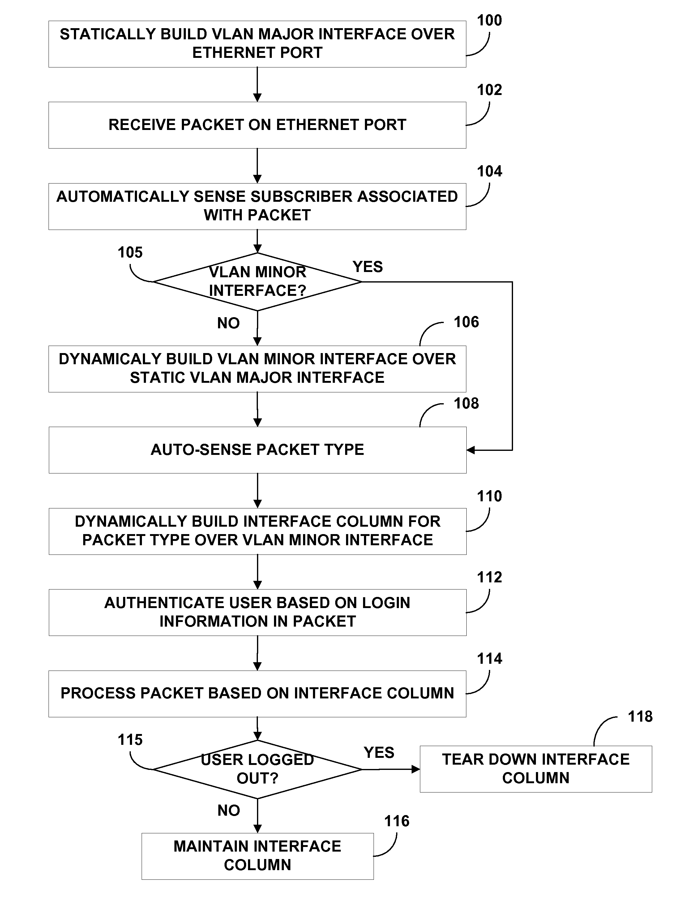
Dynamic virtual local area network (VLAN) interface configuration
a virtual local area network and interface configuration technology, applied in the field of computer networks, can solve the problems of large network time and resources, delay in the network, and bottlenecks in the provisioning of subscribers at the network device, so as to increase the rate and increase the rate
- Summary
- Abstract
- Description
- Claims
- Application Information
AI Technical Summary
Benefits of technology
Problems solved by technology
Method used
Image

Examples
Embodiment Construction
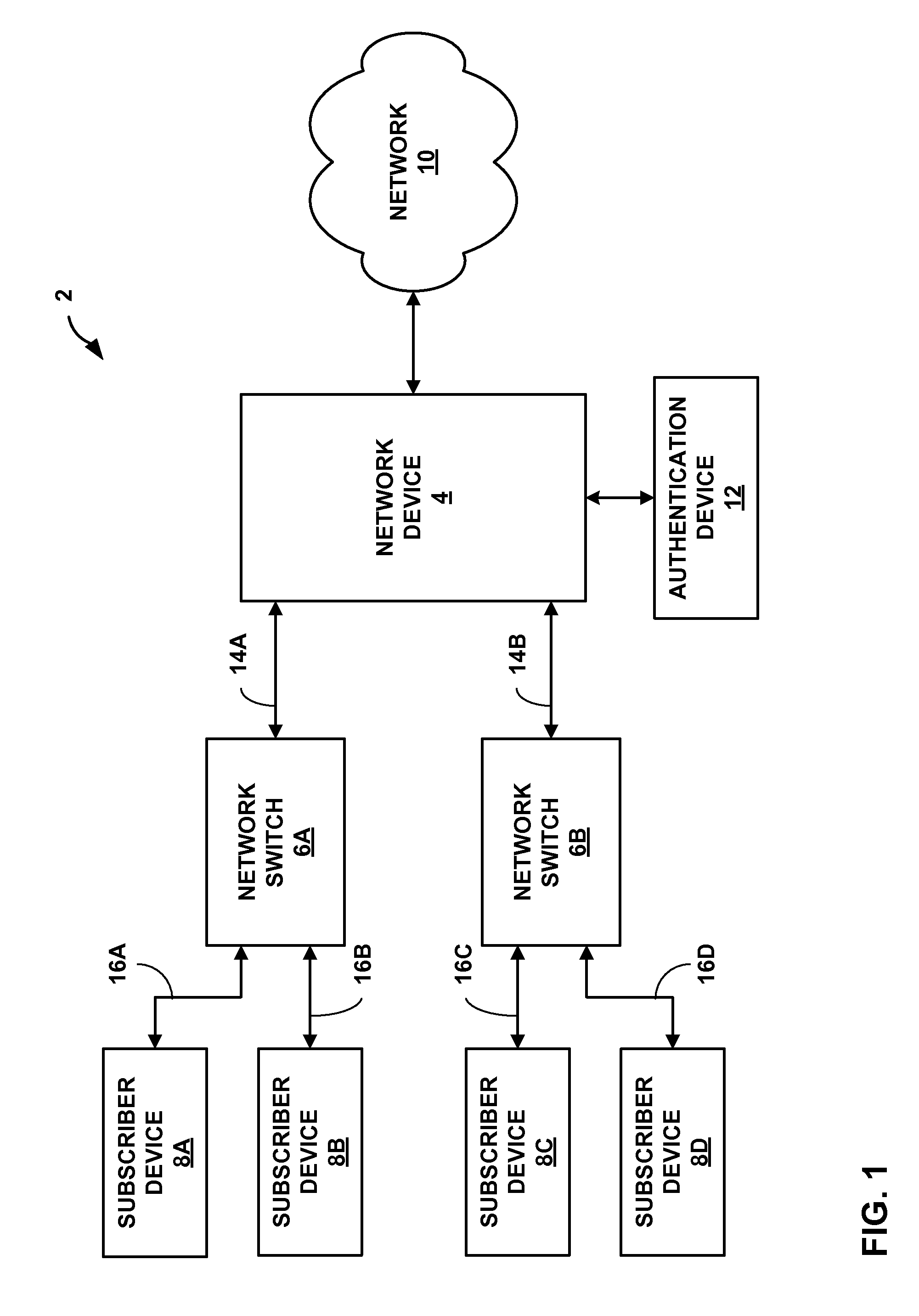
FIG. 1 is a block diagram illustrating an exemplary system 2 in which a network device 4 provides subscriber devices 8A-8D (“subscriber devices 8”) with connectivity to a network 10. System 2 comprises an Ethernet infrastructure. In other embodiments, system 2 may comprise another layer 2 protocol infrastructure, such as an Asynchronous Transfer Mode (ATM) infrastructure. Subscriber devices 8 connect to network device 4 via network switches 6A and 6B (“network switches 6”). Network switches 6 transfer Ethernet packets received from subscriber device 8 to network device 4 over Ethernet virtual local area networks (VLANs).
In the illustrated example embodiment, the invention provides techniques for dynamically building an Ethernet VLAN interface in network device 4. For example, the Ethernet VLAN interface may comprise one of a Fast Ethernet interface, a Gigabit Ethernet interface, a 10-Gigabit Ethernet interface or any other type of Ethernet network interface. The techniques described...
PUM
 Abstract
Description
Claims
Application Information