Medical sharps retardation apparatus and a method of retarding medical sharps from future use

a technology of medical sharps and retardation apparatus, which is applied in the direction of packaging, intravenous devices, other accessories, etc., can solve the problems of too detailed prior art to allow for fast or automated assembly, and achieve the effects of convenient assembly, increased gripping strength, and more secur

Inactive Publication Date: 2011-07-26
GRIFF INDS
View PDF38 Cites 3 Cited by
  • Summary
  • Abstract
  • Description
  • Claims
  • Application Information

AI Technical Summary

Benefits of technology

[0009]It is the primary object of this invention to disclose an improved needle retarding apparatus, especially one which involves the apparatus described hereinafter, wherein this new invention creates a apparatus which is cheaper, more secure, with greater gripping strength and is more easily assembled then is currently available. It is a further object of this invention to create a apparatus for this purpose that is easier to use for both the medical professional and the common layman, both of whom are forced to deal with the smaller, shorter single use needles. It is desirable that this invention creates an apparatus which is not associated with any of the problems that are aforementioned in detail, such as having to install the apparatus onto an exposed needle or having the possibility of contaminated fluids escaping from the sharps device into an area where it might contaminate others. It is a further object of this invention to create a apparatus that will conform to OSHA guidelines of single handed use and permanent retardation from future use of single use needles. It is a further object of this apparatus to be designed so that the individual pieces that make up the unit can be injection molded using thermoplastic materials. It is a further object of this apparatus to double the gripping strength by having two entities gripping the needle rather than only one entity as in the prior art. It is a further object of this invention is to design such a apparatus that can be produced as a single version or a apparatus with multiple entry points for multiple needles to use as in the field as in the operating room, multiple needles are often used in quick succession requiring many sharps to protect quickly.
[0012]The housing of the apparatus consists of an open end and a closed end. The housing consists of two pieces that forms one encasement, one piece which is the upper body and the second piece is the lower lid. The upper housing contains pivot means upon which the gripping means rotate thereupon, eliminating the need for a separate wedging element that is found in the prior art and forming a fulcrum of mechanical leverage. The encasement is constructed of such material that the material is capable of being conjoined together to create a hermetic seal, while being strong enough to prevent the medical sharp from protruding from the lower lid when the medical sharp in inserted to the apparatus with significant physical force. In the preferred embodiment, the material is a polymer such as ABS. The encasement also contains the gripping means and the enveloping containment member which are assembled into the upper housing. The gripping means consists of circular members which has embossed upon it a pattern of cross-hatching or angular grooves that are sufficient in depth and width to hold the sharp that is placed into the encasement. In the preferred embodiment, the gripping means are constructed of two round stainless steel wheels with flat sides with a circular perimeter with a knurling pattern approximately 0.0005 of an inch deep applied prior to heat-treatment of the wheels. Another gripping means that can be used are spherical stainless steel objects with a similar knurl applied. The term knurling will be understood by those having knowledge in the art, as a means for changing the surface texture of an object by the addition of series of small ridges or beads to create small protuberances increasing the surface area of the object. The direction of the bias on the gripping means is not critical as the multiple gripping means act in unison to create the leverage necessary to prevent the sharp from being removed from the apparatus. This invention eliminates the number of pieces that must be carefully inserted. Prior art is too detail oriented to allow for fast or automated assembly. The current invention eliminates the need for detailed orientation of the pieces, allowing for faster or automated assembly.
[0013]The enveloping containment member is constructed of a polymer which is soft enough to accept the injection of the sharp thereinto, yet is firm enough to hold the gripping means in location prior to the insertion of the sharp into the apparatus. The enveloping containment member must be of such material that it envelopes that portion of the medical sharp injected thereinto, and such that there is created a seal whereby any fluids contained thereon or therein the medical sharp is prevented from escaping from the encasement. In the preferred embodiment, a polyvinylchloride, with a Shore A hardness between 45-70 preferably 54, material is used. The enveloping containment member is specially shaped with circular protrusions that hold the gripping means in place against the interior of the upper body. The protrusions must be designed as such to allow the gripping means to relocate laterally upon the insertion of the medical sharp, but not to the extent, as to prevent the gripping means from not tangentially contacting the medical sharp at all times. The circular design of this enveloping member is another improvement over the prior art. The prior art has an enveloping member that must be strategically placed into the housing so that the single gripping means will function properly. This detailed placement makes for a less efficient and productive construction of the prior art devices, and makes automation of the assembly of the prior art device more costly, if at all. The current invention's enveloping member is not locationally unique, so any orientation of the enveloping member by human assemblers or an automated device is simply performed. This enveloping containment member is shaped in such a manner as to allow both the protrusions and the target area to be shaped in such a manner to allow the medical sharp to be enveloped by the target area following the medical sharps contour as well as providing space for the protrusions to engage the gripping means. An embodiment of this invention is a wrench that has a gripping slot which integrates with current needle hub and syringe designs, whereby the gripping slot adepts into the ribs of the needle hub, securing a fit that enables the user to hold the cover and rotate the syringe body and remove the needle and the needle hub from the syringe body. Future designs of the wrench will facilitate upgrades in hub designs.

Problems solved by technology

Prior art is too detail oriented to allow for fast or automated assembly.

Method used


Image

  • Medical sharps retardation apparatus and a method of retarding medical sharps from future use
  • Medical sharps retardation apparatus and a method of retarding medical sharps from future use
  • Medical sharps retardation apparatus and a method of retarding medical sharps from future use

Examples


Embodiment Construction

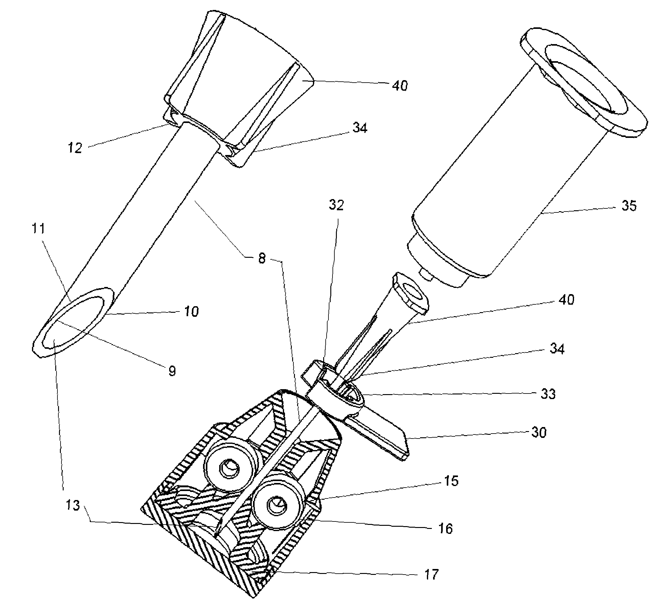
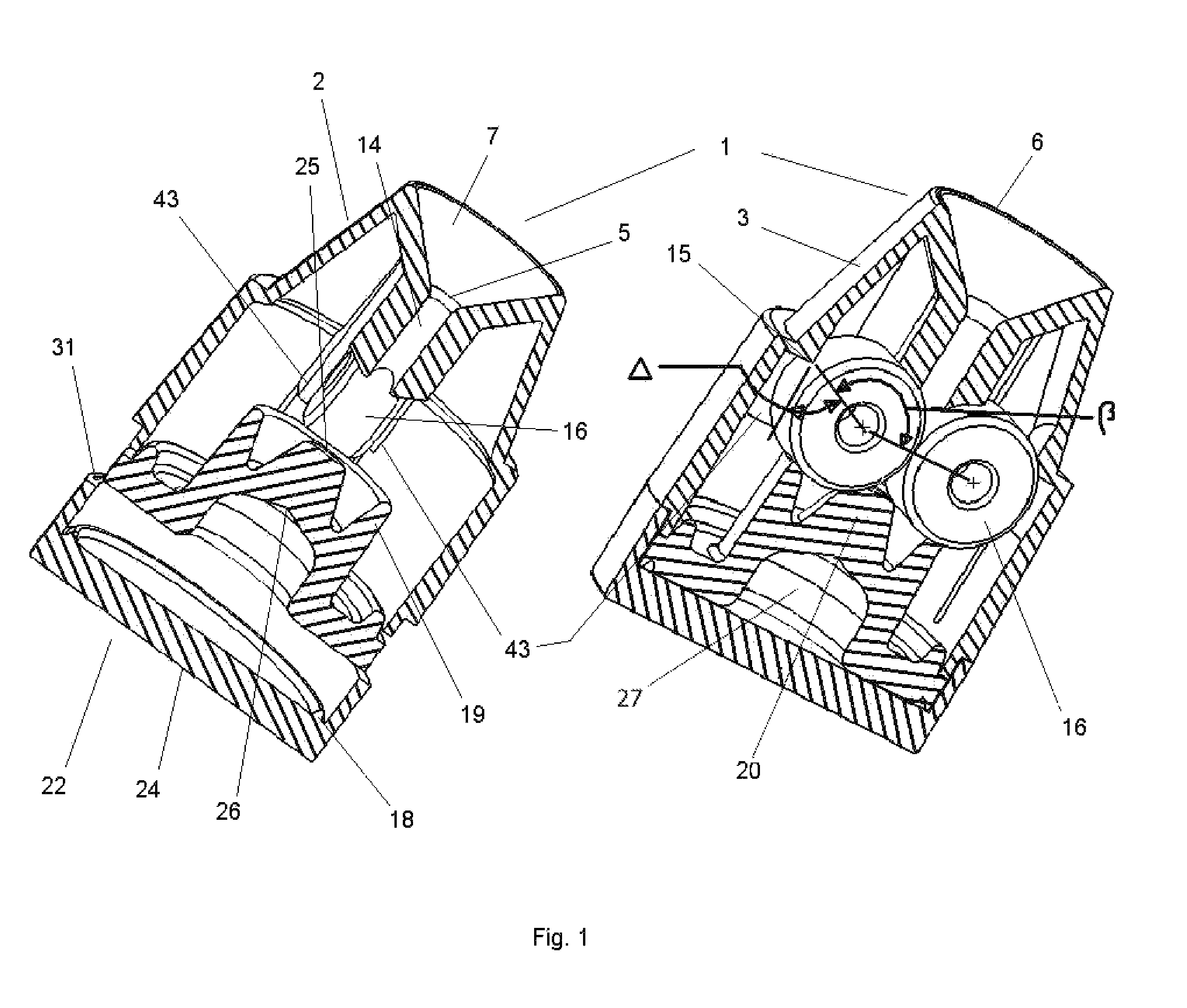
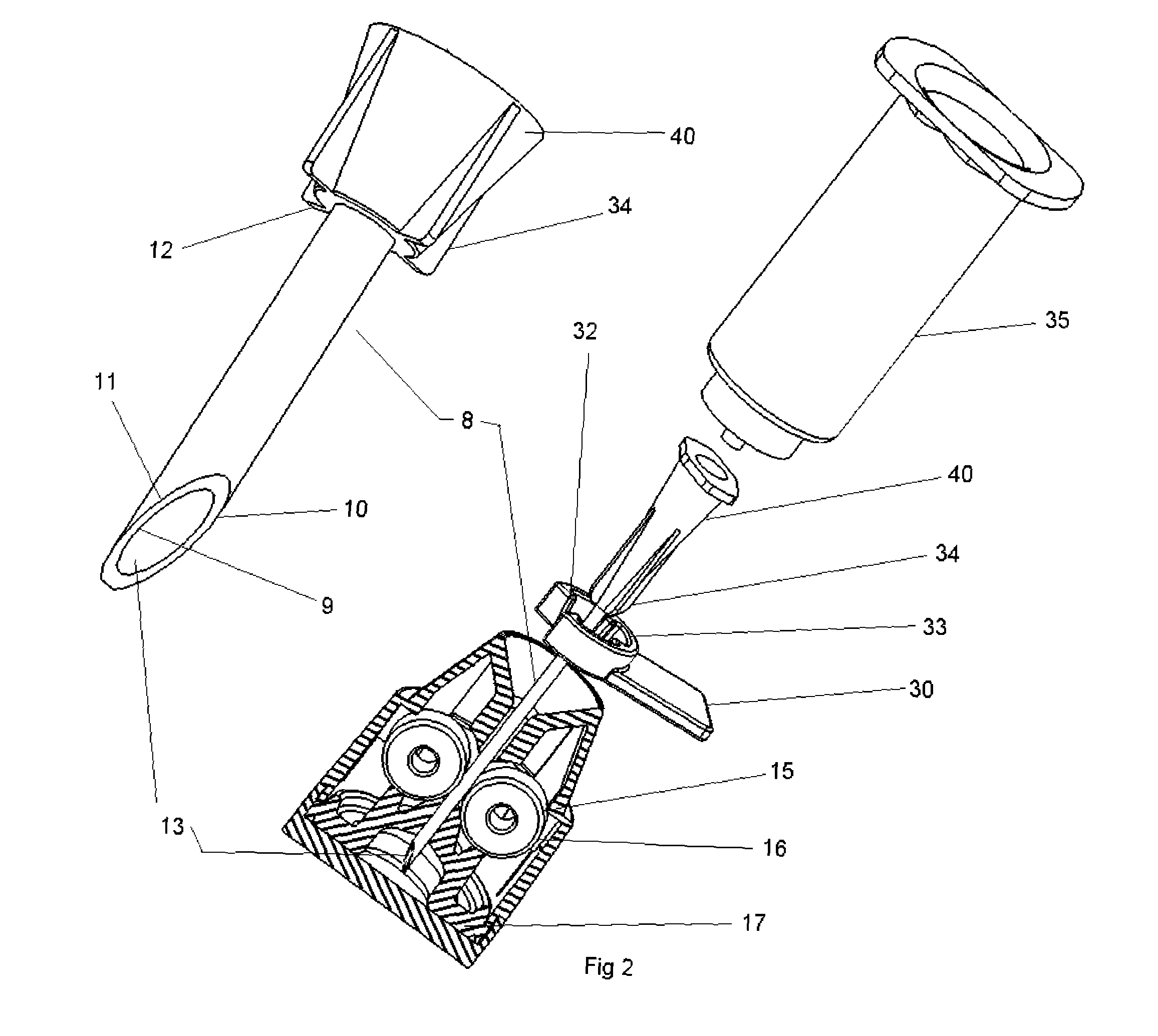
[0023]In FIG. 1, the encasement of apparatus 1 is shown in cross-sectional views. In FIGS. 2 and 3, the details of the invention are shown exploded and in use. Upper housing 2, contains an exterior portion 3, along with an interior portion 4 with sharps entrance opening 5 that is located subjacent to targeting ring 6. Interior portion 4 symmetrical about the centerline of the apparatus. Both upper housing 2 and bottom encasement lid 22 are designed such that they are able to be injection molded using thermoplastics. Sharps entrance 5 is located on the closed end of upper housing unit 2 which is opposite to open end of upper housing unit 2. Bottom lid 22 has an interior surface 23 and an exterior surface 24. FIG. 4 shows the locating means shown here as targeting ring 6 that is connected to sharps entrance open 5 by centering slope 7, which is angled in an acute manner that serves as a positioning of the medical sharp into the proper orientation for insertion through sharps entrance ...


PUM


Abstract

A medical apparatus whose purpose it is to permanently retard future use of a medical apparatus, in particular needles, preventing accidental exposure to contaminated sharps. It facilitates the possible removal of medical devices from their respective holders, while preventing possible contaminated discharge of fluids located along the anterior or exterior walls of needles or exterior of medical sharps. This medical apparatus provides for single handed use which complies with OSHA guidelines, and its advanced design facilitates the more common shorter medical needles to which non-medical users are accustomed as well as the wide range of needles that medical professional use. This apparatus is easier to manufacture, shorter in stature that allows for its inclusion in the already overcrowded medical trays used by today's medical personnel, in particular, emergency medical technicians. An embodiment contains multiple apparatuses together allowing for safe storage of several sharps, which is a common need in emergency situations both in the field and in the hospital settings, where doctors or technicians are attempting to stabilize critical patients with multiple injections. The apparatus uses counter-opposing gripping devices with an enveloping containment member which serves both to tension the juxtapositionally aligned gripping devices and to prevent leakage of contaminated fluids from medical devices.

Description

BACKGROUND OF INVENTION[0001]Since the knowledge that blood borne pathogens and diseases can be passed from the carrier to another being, science has been concerned about the possibility of accidental needle puncture by unshielded sharp needles. Recently with the advent of the spread of AIDS and Hepatitis strains through blood contact, there has been added emphasis on the need to prevent accidental needle puncture by those using the needles or by those whose task it is to dispose of used needles. Also there exist a need to prevent secondary use of hypodermic style needles by those outside of the medicinal users, such as intravenous drug abusers, in the prevention to reduce the spread of these diseases that are spread by contact with contaminated blood. As technology has improved, so has the ability for needle manufacturer to develop sharper needles with smaller bores, increasing the chance of accidental puncture by these smaller sharper needles. Technology has also increased the saf...

Claims


Application Information

Patent Timeline
Patent Type & Authority Patents(United States)
IPC IPC(8): B65D83/10
CPCA61M5/3205
Inventor GABA, RODOLFOGRIFFIN, MICHAEL D
Owner GRIFF INDS
Why Eureka
Try Eureka