Method for making field emission lamp

a field emission lamp and emission technology, applied in the manufacture of electric discharge tubes/lamps, non-electron-emitting electrode materials, discharge tubes luminescnet screens, etc., can solve the problems of incandescent lamps, low energy efficiency, and most of the electric energy used to power lamps

Active Publication Date: 2011-07-26
TSINGHUA UNIV +1
View PDF6 Cites 1 Cited by
  • Summary
  • Abstract
  • Description
  • Claims
  • Application Information

AI Technical Summary

Benefits of technology

[0009]Conventionally, the fabrication of the field emission lamp includes the process of fabricating the cathode emitters, forming the anode, and encapsulating the glass tube. The encapsulation procedure includes connecting the glass feedthroughs with the ends of the glass tube to seal the glass tube. Currently, a colloid is used to connect the glass feedthroughs to the glass tube. However, this sealing method has a poor encapsulation effect and thus affects the performance life of the field emission lamp. Moreover, this method is complicated and time-consuming and not suitable for mass production of the field emission lamp. And thus the field emission lamp has a relatively high cost.

Problems solved by technology

However, an incandescent lamp emits light by the heating of a tungsten filament and most of the electric energy used to power the lamp is converted into heat and thereby wasted.
Therefore, a main shortcoming of the incandescent lamp is the low energy efficiency.
However, when the glass tube is broken, the mercury vapor is prone to leak out therefrom, and thus, is poisonous and noxious to humans and is environmentally unsafe.
However, this sealing method has a poor encapsulation effect and thus affects the performance life of the field emission lamp.
Moreover, this method is complicated and time-consuming and not suitable for mass production of the field emission lamp.
And thus the field emission lamp has a relatively high cost.

Method used


Image

  • Method for making field emission lamp
  • Method for making field emission lamp
  • Method for making field emission lamp

Examples


Embodiment Construction

[0018]Reference will now be made to the drawings to describe, in detail, embodiments of the present method for making a field emission lamp.

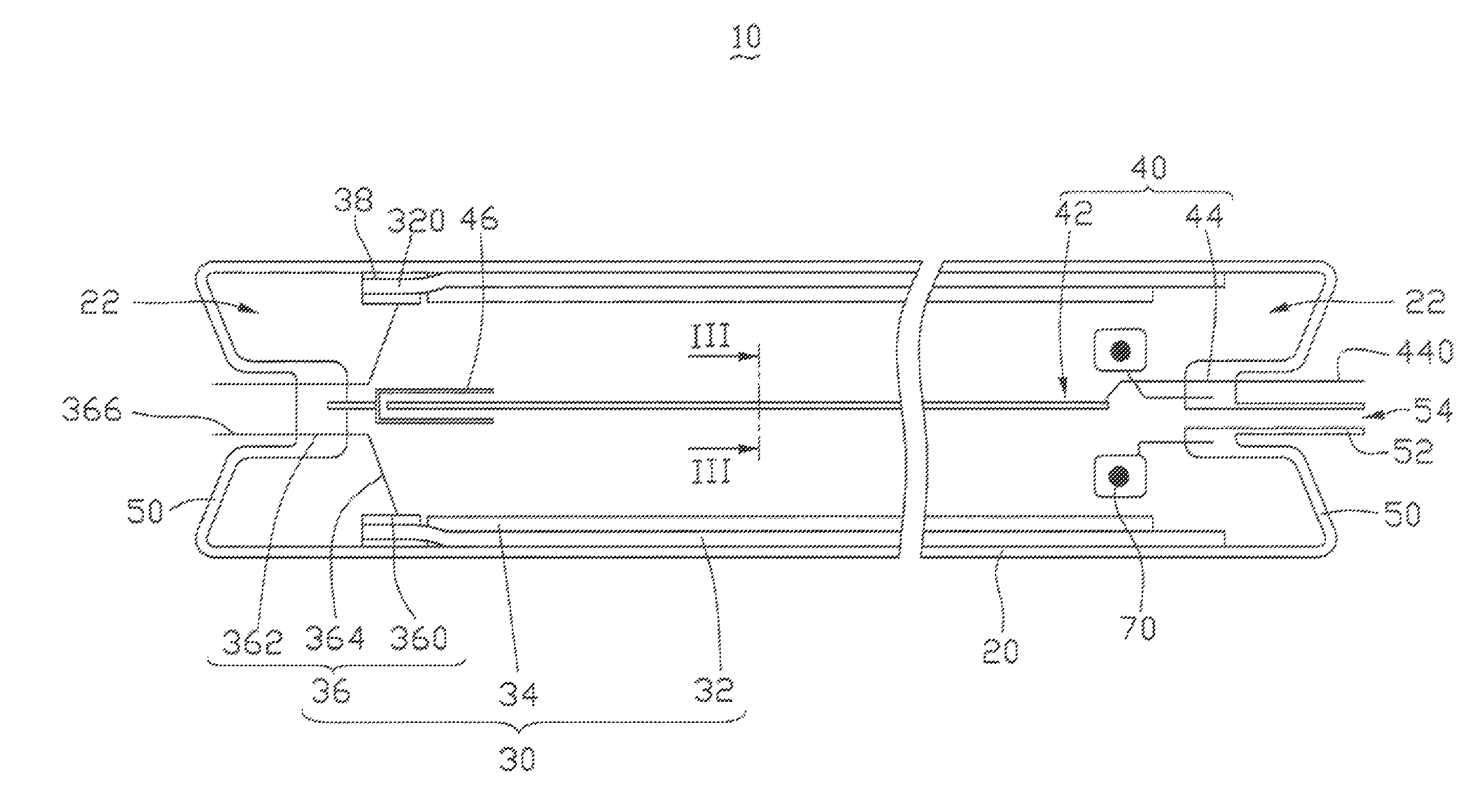
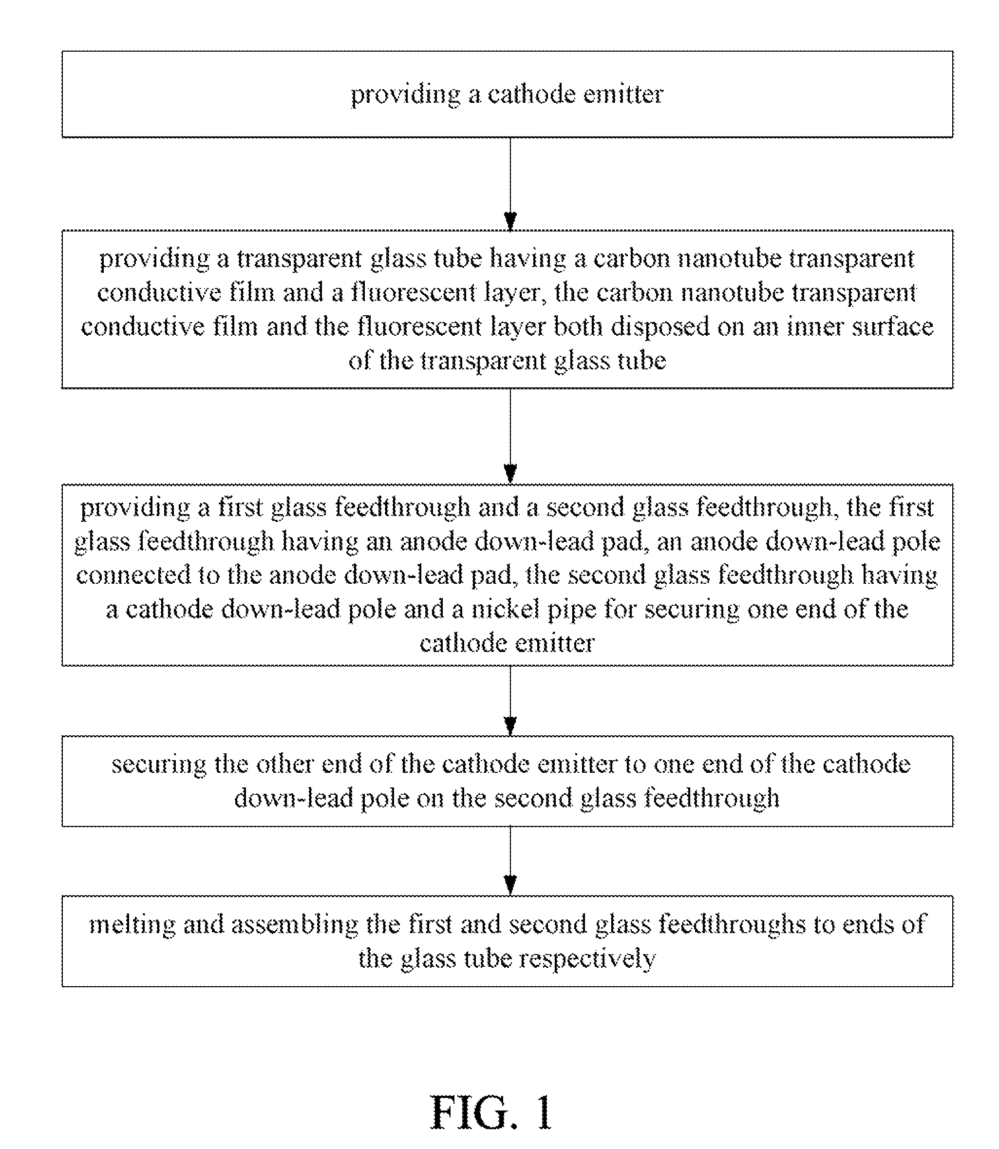
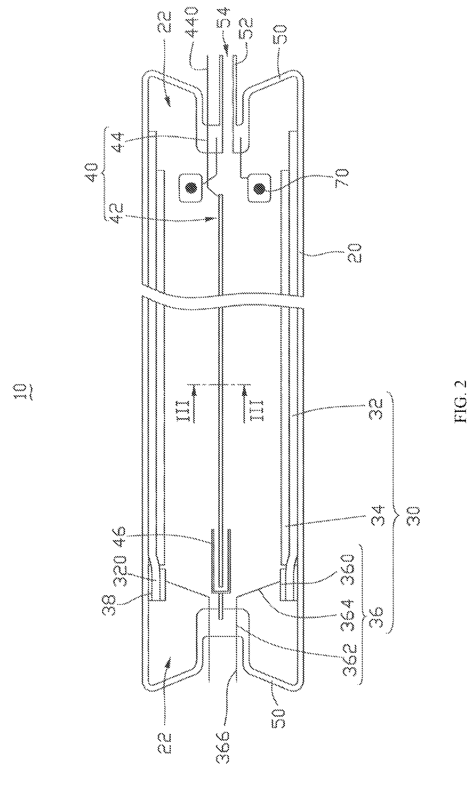
[0019]Referring to FIG. 1, a method for making a field emission lamp, in accordance with a first embodiment, generally includes the steps of: (a) providing a cathode emitter; (b) providing a transparent glass tube having a carbon nanotube transparent conductive film and a fluorescent layer, wherein the carbon nanotube transparent conductive film and the fluorescent layer are both disposed on an inner surface of the transparent glass tube; (c) providing a first glass feedthrough, a second glass feedthrough, and a nickel pipe, wherein the first glass feedthrough has an anode down-lead pad and an anode down-lead pole connected to the anode down-lead pad, and the second glass feedthrough has a cathode down-lead pole; (d) securing the nickel pipe to a first end of the cathode emitter and securing a second end of the cathode emitter to one end of the ...


PUM

PropertyMeasurementUnit
temperatureaaaaaaaaaa

Abstract

A method for making a field emission lamp generally includes the steps of: (a) providing a cathode emitter; (b) providing a transparent glass tube having a carbon nanotube transparent conductive film and a fluorescent layer, wherein the carbon nanotube transparent conductive film and the fluorescent layer are both disposed on an inner surface of the transparent glass tube; (c) providing a first glass feedthrough, a second glass feedthrough, and a nickel pipe, wherein the first glass feedthrough has an anode down-lead pad and an anode down-lead pole connected to the anode down-lead pad, and the second glass feedthrough has a cathode down-lead pole; (d) securing the nickel pipe to one end of the cathode emitter and securing the other end of the cathode emitter to one end of the cathode down-lead pole of the second glass feedthrough; and (e) melting and assembling the first and second glass feedthroughs to ends of the transparent glass tube respectively.

Description

RELATED APPLICATIONS[0001]This application is related to commonly-assigned application Ser. No. 11 / 951,160, entitled, “FIELD EMISSION LAMP AND METHOD FOR MAKING THE SAME,” filed on Dec. 5, 2007, which is now patented as U.S. Pat. No. 7,780,495. Disclosure of the above-identified application is incorporated herein by reference.BACKGROUND[0002]1. Field of the Invention[0003]The invention relates to a method for making a field emission lamp.[0004]2. Discussion of Related Art[0005]Electrical lamps for daily living usually include incandescent lamps and fluorescent lamps. Since Thomas Edison invented the first viable incandescent lamps in 1879, the incandescent lamps have a long history for simple fabrication thereof. However, an incandescent lamp emits light by the heating of a tungsten filament and most of the electric energy used to power the lamp is converted into heat and thereby wasted. Therefore, a main shortcoming of the incandescent lamp is the low energy efficiency. Thus, the f...

Claims


Application Information

Patent Timeline
Patent Type & Authority Patents(United States)
IPC IPC(8): H01J19/00H01J19/24H01J19/02
CPCH01J9/26H01J63/02
Inventor WEI, YANGXIAO, LINZHU, FENGLIU, LIANGFAN, SHOU-SHAN
Owner TSINGHUA UNIV
Why Eureka
Try Eureka