Method for recording an examination object

a technology for recording objects and examinations, applied in tomography, instruments, applications, etc., can solve the problems of limiting the size of flat panel detectors in the past, and achieve the effect of low radiation loading on examination objects

Inactive Publication Date: 2011-07-26
SIEMENS HEALTHCARE GMBH
View PDF12 Cites 6 Cited by
  • Summary
  • Abstract
  • Description
  • Claims
  • Application Information

AI Technical Summary

Benefits of technology

[0006]It is the task of the invention to provide a large-volume method for recording a large and / or difficult-to-access examination object which will keep the radiation loading on the examination object as low as possible.
[0010]Through the reduced rotations in the method in accordance with the invention by at least one angle of rotation of β0 compared with the known acquisition methods a distinctly lower x-ray dose is applied to the examination object. As a result the radiation loading for the patient and for the examining personnel is reduced. Furthermore, through the method in accordance with the invention a 360° rotation does not have to be performed, which means that the examination procedure is much less complex.

Problems solved by technology

Since flat panel detectors with a maximum size of 30×40 cm are generally used here, the size of the flat panel detector thus represented a limitation in the past.
This method requires, however, that the x-ray device can record through 360° when the x-ray detector is displaced, which—despite all the flexibility of an industrial robot—is frequently not the case, in particular where patients are involved.

Method used


Image

  • Method for recording an examination object
  • Method for recording an examination object
  • Method for recording an examination object

Examples


Embodiment Construction

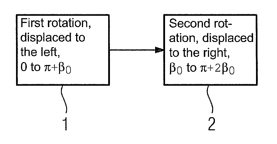
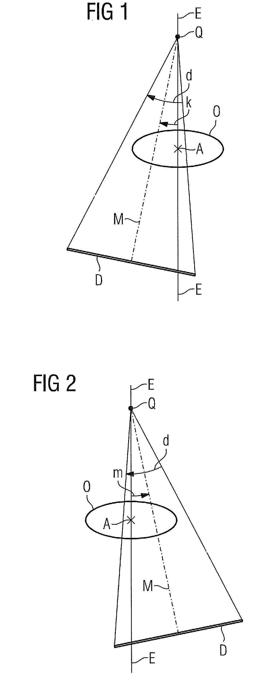
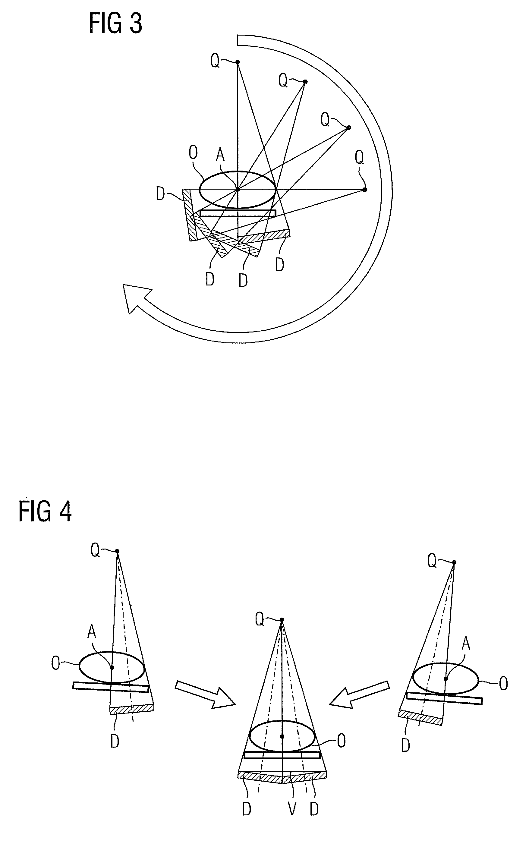
[0025]Using flexible C-arm x-ray devices x-ray images can be recorded during a common rotation of an x-ray source Q and an x-ray detector D about an axis of rotation A (mostly in the area of the examination object) and used for a tomographic reconstruction. In the known large-volume method for recording 3D images of particularly large examination objects O the recording range is increased by recording two x-ray images for each position of the x-ray source Q using an x-ray detector D displaced in two different, opposite directions (e.g. to the “left” and to the “right”). This is frequently carried out by means of two consecutive rotations, whereby in the first rotation the x-ray detector is displaced in a first direction (e.g. to the left) and in the second rotation is displaced in the opposite second direction (e.g. to the right). The two x-ray images can then be combined to create a total image and the plurality of various total images can be reconstructed to form a 3D image.

[0026]...


PUM


Abstract

A method is provided for recording an examination object using an x-ray recording system having an x-ray source and an x-ray detector rotatable about a common axis of rotation. X-ray detector is displaced in a first direction enclosing a first angle k between a perpendicular bisector from x-ray source to x-ray detector and a plane running through x-ray source and containing the axis, k≠0. First x-ray images are recorded in angular positions of x-ray source and x-ray detector displaced in the first direction in a first rotation. X-ray detector is displaced in a second direction enclosing a second angle m between the bisector and the plane, m≠0 and is on an opposite side from k. Starting points of the rotations are differed by an angle of displacementβ0=k+m+d2,where d is the detector fan angle. Starting points and finishing points of the rotations are spanned by π+β0.

Description

CROSS REFERENCE TO RELATED APPLICATIONS[0001]This application claims priority of German application No. 10 2009 038 787.0 filed Aug. 25, 2009, which is incorporated by reference herein in its entirety.FIELD OF THE INVENTION[0002]The invention relates to a method for recording an examination object comprising an x-ray recording system which can be rotated about a shared axis of rotation and comprises an x-ray source and an x-ray detector.BACKGROUND OF THE INVENTION[0003]In addition to the known computer tomography, x-ray projections disposed on a circle can be recorded with the aid of C-arm x-ray devices and used for a tomography reconstruction. Since flat panel detectors with a maximum size of 30×40 cm are generally used here, the size of the flat panel detector thus represented a limitation in the past. This was solved in that the movement of the C-arm in novel C-arm x-ray devices takes place by means of an industrial robot. New and also complicated recording movements are herewith...

Claims


Application Information

Patent Timeline
Patent Type & Authority Patents(United States)
IPC IPC(8): A61B6/00
CPCA61B6/032A61B6/5241G01N23/046G01N2223/33G01N2223/419
Inventor KUNZE, HOLGER
Owner SIEMENS HEALTHCARE GMBH
Why Eureka
Try Eureka