Watershed runoff treatment device & method

a runoff treatment and runoff technology, applied in water cleaning, separation processes, filtration separation, etc., can solve the problems of limiting the use of the most efficient hydraulic drain inlet insert device, requiring more complex equipment and expensive equipment, and not only more expensive providing these capabilities

Inactive Publication Date: 2011-08-02
STORMWATER FILTERS
View PDF10 Cites 10 Cited by
  • Summary
  • Abstract
  • Description
  • Claims
  • Application Information

AI Technical Summary

Benefits of technology

[0008]Three, the flow control chamber may also include an exit opening on an outlet side of the chamber, and an internal flow diverting member between the inlet side and the outlet side. For example, the outlet side may be essentially entirely absent of any wall structure forming the exit opening. This facilitates aligning the exit opening with the vault outlet.
[0012]Seven, the device may include a gravity drain-down pathway to an appropriate final discharge point such as another similar drain inlet vault, an external pump sump, an infiltration or detention structure or an offsite discharge pathway. The pathway may have a piping connection inlet within the space and below the horizontal filter array. The piping connection inlet may comprise a closed end turned-down element with holes therein positioned with the space to provide a gravity discharge flow through such pipe connection to be within a predetermined flow rate range to retain the floating hydrocarbon collection media within the space.
[0015]This method of treating watershed runoff and this watershed drainage device is, in terms of project-life-cost, economic to install in a drain inlet vault. This storm watershed drainage device converts a single-stage catch basin vault into a two-stage gravity clarifier. By producing temporarily standing water for more efficient gravity separation and then eliminating the standing water (once rainfall and storm water runoff has slowed sufficiently). This is done in a short enough time to prevent flying mosquito development even if eggs, larvae or pupae are washed into the drain inlet vault with watershed runoff. This device enables the capture, detention, removal and disposal of contaminants contained in watershed runoff entering drain inlet vaults in which such devices have been installed to ensure compliance with environmental regulations. These functions are achieved thorough the use of gravity separation to enable collection of entrained suspended solids and sorbent media deployment for collection of floatable hydrocarbons, while at the same time preventing mosquito development in the standing water by automatically removing standing water once rainfall and storm water runoff have ceased.
[0016]This method provides for maximum possible collection of settled TSS within a single-stage drain inlet vault (catch basin) by converting the single-stage drain inlet vault into a two-stage gravity clarifier. Further, it provides for maximum collection / removal of TOG entrained in the influent water and it enables disposal of collected TOG in a Class-A landfill to be possible. Embodiments of this method also provide for inspection, determination of need for, and accomplishment of cleanout and disposal of captured contaminants from drain inlet vaults using the storm water treatment devices of this invention. Property developments using this device and method and will remain functionally compliant with governmental environmental regulations throughout the life of their land development project and minimize project-life-costs associated with such storm water treatment.

Problems solved by technology

Devices are generally available to satisfy the requirements for trash discharge control, but control of smaller, more complex suspended solids and hydrocarbon-based contaminants require equipment that is more complex and expensive, so much so, that the trend for some time has been for property developers to use drain inlet inserts which can be fitted into even the smallest sizes of drain inlet vaults.
These inserts can be efficient for trash removal and less so for smaller sizes of TSS particulate or TOG, but they are less expensive, readily available, and since standards for acceptability of such BMP's have not yet been fully promulgated or adopted, are not prohibited by many city / county plan check functions.
Providing these capabilities is not only more expensive, but also introduces an additional problem which is beginning to limit use of the most efficient hydraulic drain inlet insert devices, such as the Hydro-Cartridge (U.S. Pat. No. 5,297,367).
Namely, the problem of such standing water providing an environment for mosquito growth.

Method used


Image

  • Watershed runoff treatment device & method
  • Watershed runoff treatment device & method
  • Watershed runoff treatment device & method

Examples


second embodiment

[0023]FIG. 5 is an elevation view of the device of FIG. 2 installed in the vault of FIG. 1

third embodiment

[0024]FIG. 6 is an elevation view of the device of FIG. 2 installed in the vault of FIG. 1.

DETAILED DESCRIPTION OF SOME ILLUSTRATIVE EMBODIMENTS

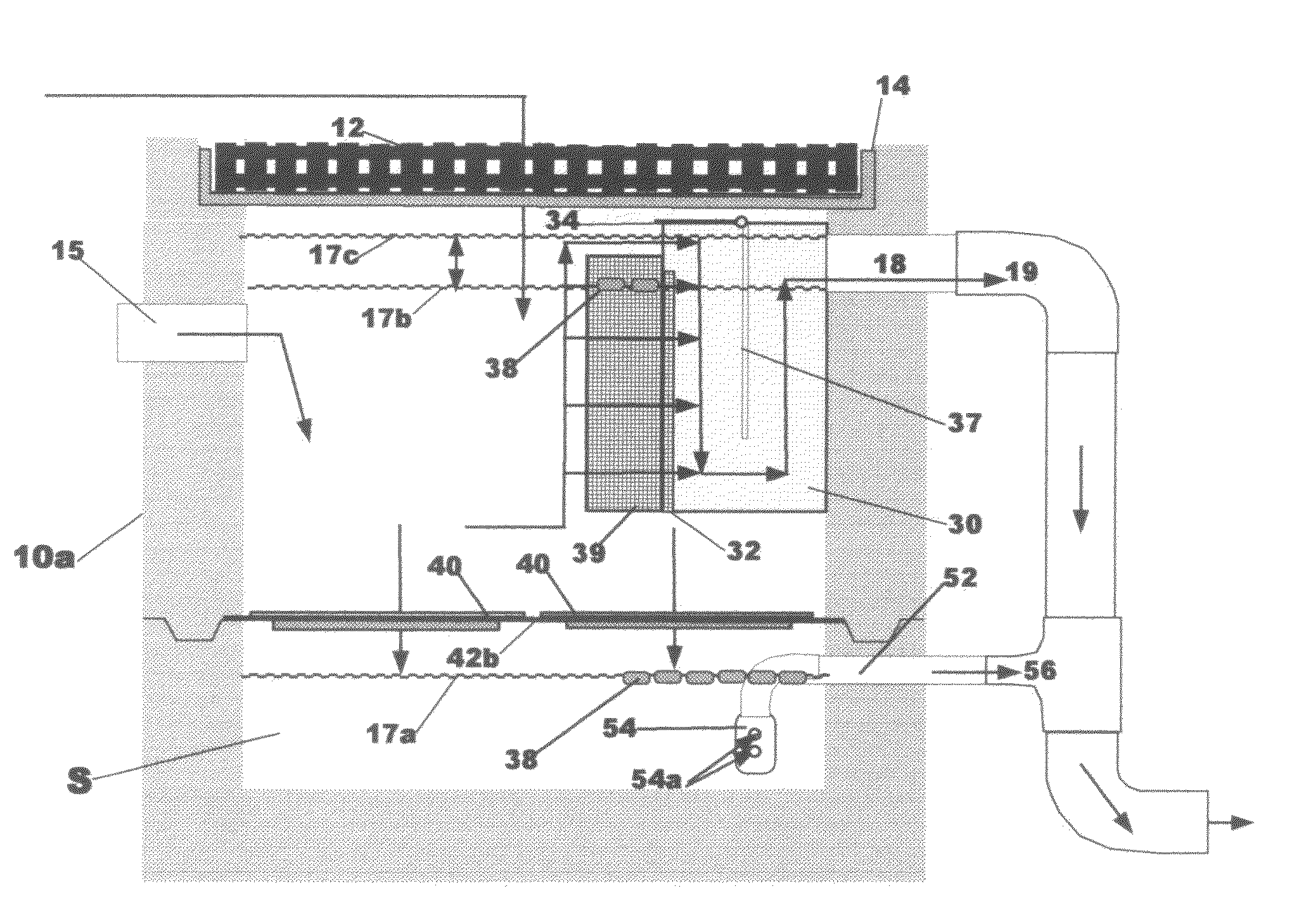
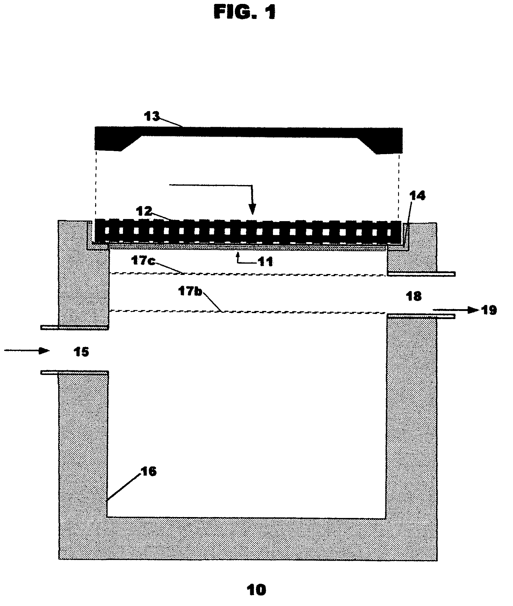
[0025]FIG. 1 discloses the top / side-entry, high-side-exit, concrete drain inlet vault 10 of a type in which the embodiments of this invention can typically be utilized. This type of drain inlet vault 10 consists typically, but not exclusively, of a concrete square or rectangular shaped box 16 with the open top 11 surrounded by steel angular support elements 14 which position and support grated lid(s) 12 or solid cover(s) 13. The vault 10 may have a top-entry grate 12 through which storm water runoff from the surrounding watershed enters the inlet vault 10, or it may have side-entry port(s) 15, or both. Water can enter the box 16 through the open top 11 or through pipe(s) 15 penetrating the sidewall(s) of box 16. Water can exit the box 16 through pipe(s) 18 located as high as possible in a sidewall of box 16 and become discharge 19. The water...


PUM

PropertyMeasurementUnit
flow rateaaaaaaaaaa
flow ratesaaaaaaaaaa
pressureaaaaaaaaaa

Abstract

A watershed runoff treatment device is adapted to be used to convert a single-stage drain inlet vault (catch basin) into a two-stage clarifier in which treatment can be accomplished before discharging the water to further on-site treatment or detention or to storm drain. It includes a flow control box member to be mounted on the interior of the vault covering the discharge pipe(s) so that substantially all water runoff entering the vault must flow therethrough prior to exiting the vault. Floating, disposable hydrocarbon collection pads are deployed inside an open mesh container removably attached and covering the upstream face of the flow control box, as well as below the horizontal filter array described next. A horizontal filter array with removable, cleanable filter media is deployed below the flow control box for collection of suspended solids gravity-settling within the vault space, and enabling standing water in the vault interior to gravity flow through the permeable filter and suspended solids and automatically discharge from the vault, thus providing mosquito control and de-watering of solids for easy removal.

Description

RELATED PATENT APPLICATIONS & INCORPORATION BY REFERENCE[0001]This application claims the benefit under 35 USC 119(e) of U.S. provisional patent application Ser. No. 60 / 943,722, entitled “Watershed Runoff Treatment Device & Method,” filed Jun. 13, 2007. This related application is incorporated herein by reference and made a part of this application. If any conflict arises between the disclosure of the invention in this utility application and that in the related provisional application, the disclosure in this utility application shall govern. Moreover, the inventors incorporate herein by reference any and all U.S. patents, U.S. patent applications cited or referred to in this application or cited or referred to in the U.S. patents and U.S. patent applications incorporated herein by reference.DEFINITIONS[0002]The words “comprising,”“having,”“containing,” and “including,” and other forms thereof, are intended to be equivalent in meaning and be open ended in that an item or items follo...

Claims


Application Information

Patent Timeline
Patent Type & Authority Patents(United States)
IPC IPC(8): E03F5/16
CPCC02F1/28E03F5/0404E03F5/14C02F2101/30C02F2103/001
Inventor BELASCO, DAVID
Owner STORMWATER FILTERS
Why Eureka
Try Eureka