High visibility plasma arc torch

a plasma arc torch and high-visibility technology, applied in plasma welding apparatus, manufacturing tools, solventing apparatus, etc., can solve the problems of poor operator viewing angle, adversely affecting cutting performance, and hand held, and achieve the effect of improving the visibility of the work zon

Active Publication Date: 2011-08-02
HYPERTHERM INC
View PDF36 Cites 33 Cited by
  • Summary
  • Abstract
  • Description
  • Claims
  • Application Information

AI Technical Summary

Benefits of technology

[0011]What is needed is a torch that provides improved workpiece visibility during high temperature metal processing without sacrificing torch life, performance, or the life expectancy of torch consumables. The present invention achieves these objectives by carefully balancing the many design parameters of the torch consumables to achieve a streamlined, functional torch having a large work zone viewing angle while still maintaining performance and reliability.
[0027]Embodiments also include gas control swirl rings in which the first body portion has a first inside diameter that is different than a second inside diameter of the second body portion. The second inside diameter can be larger than the first inside diameter, e.g., to provide sufficient bearing surface to support, stabilize, and align an electrode, and to help promote improved visibility of a work zone (i.e., where the plasma arc impinges on or penetrates a workpiece). The second body portion of the electrode can also include an interior surface that is configured to slideably engage with and provide a bearing and alignment surface for supporting an adjacent internal structure, such as an electrode. The gas control swirl ring can be formed of a dielectric material.

Problems solved by technology

Bulky design results in wide configurations that have a poor operator viewing angle.
These problems are especially pronounced for manual (hand held) torches that are manipulated by an operator.
A restricted viewing angle about the torch by the operator of the torch, inhibiting his view of the cut as the workpiece is processed by the plasma, adversely affects cutting performance.
Additionally, frequently during torch operation the operator is constrained by space or obstructions that further inhibit his visibility.

Method used


Image

  • High visibility plasma arc torch
  • High visibility plasma arc torch
  • High visibility plasma arc torch

Examples


Embodiment Construction

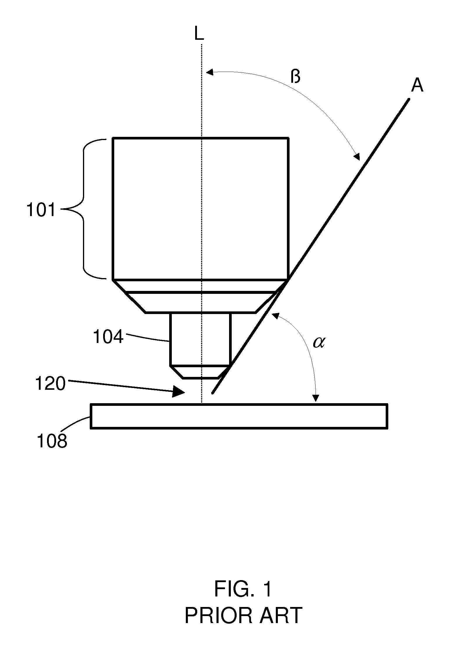
[0050]FIG. 1 is a perspective view of a torch tip of a known plasma arc torch. A nozzle 104 is held in place by a retaining cap 101 which secures the nozzle 104 to a torch body (not shown). An electrode (not shown) is disposed within the torch body. A proximal portion of the nozzle 104 is located near the workpiece 108 during operation of the torch. A viewing angle, α, of the work zone 120 extends from the surface of the workpiece 108 to reference line A. Reference line A is drawn as a tangent to the exterior surface of the torch, as shown. For a PACII OT torch, available from Hypertherm, Inc. of Hanover, N.H., the viewing angle is approximately 55° (90°-35°), as illustrated. Conversely, a work zone obstruction angle β established by this torch is 35° from a longitudinal axis of the torch L, and this obstruction angle extends outwardly in at least two directions from the torch.

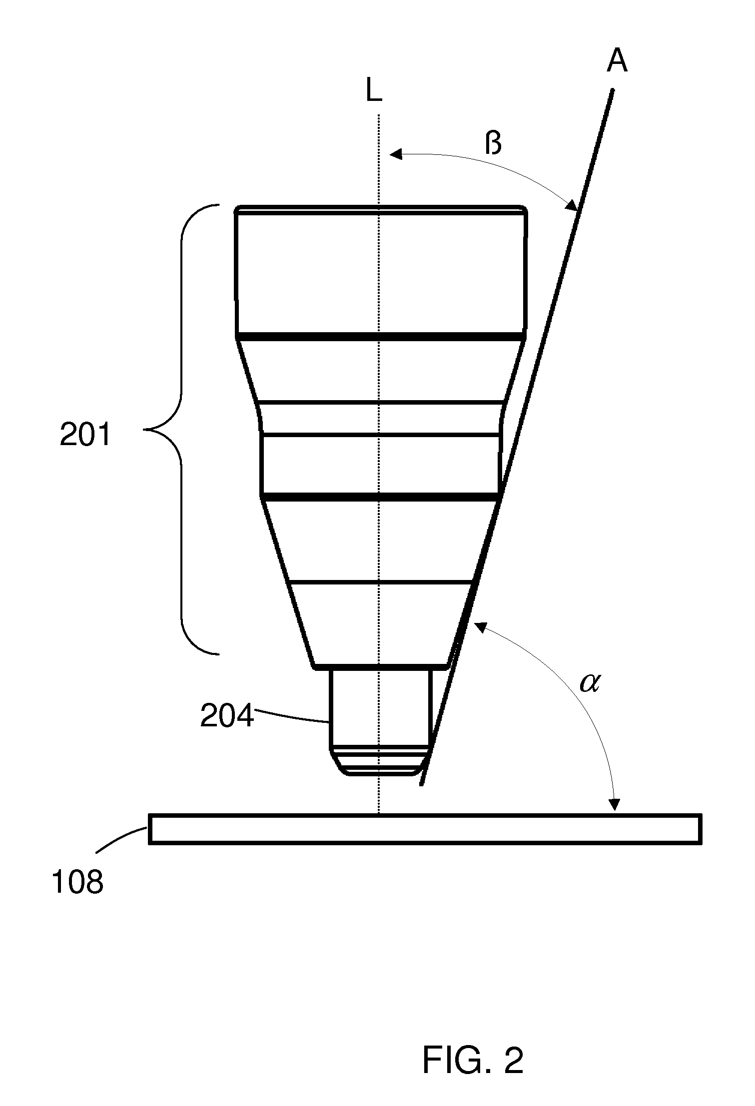
[0051]FIG. 2 is a perspective view of a torch tip of a plasma arc torch according to an embodiment of the i...


PUM

PropertyMeasurementUnit
viewing angleaaaaaaaaaa
view obstruction angleaaaaaaaaaa
angleaaaaaaaaaa

Abstract

An improved torch providing high visibility of the work zone to the operator, an increased viewing angle, and a reduced obstruction angle. The high visibility torch includes consumables adapted to maintain torch and consumables performance while reducing visual obstruction to the user, by coordinating, balancing, and optimizing design requirements and stack up tolerances. The invention also includes a related low-profile safety switch that promotes workpiece visibility and minimizes view obstruction.

Description

CROSS REFERENCES TO RELATED APPLICATIONS[0001]This application claims the benefit of U.S. Provisional Patent Application No. 60 / 825,453 filed on Sep. 13, 2006, the disclosure of which is hereby incorporated by reference.FIELD OF THE INVENTION[0002]The invention generally relates to the field of plasma arc torch systems and processes. More specifically, the invention relates to improved electrode, swirl ring and safety configurations for use in a plasma arc torches, and related methods.BACKGROUND OF THE INVENTION[0003]Plasma arc torches are widely used for the high temperature processing (e.g., cutting, welding, and marking) of metallic materials. A plasma arc torch generally includes a torch body, an electrode mounted within the body, an emissive insert disposed within a bore of the electrode, a nozzle with a central exit orifice, a shield, electrical connections, passages for cooling and arc control fluids, a swirl ring to control the fluid flow patterns, and a power supply. The to...

Claims


Application Information

Patent Timeline
Patent Type & Authority Patents(United States)
IPC IPC(8): B23K10/00
CPCH05H1/34H05H2001/3478H05H1/3478
Inventor TWAROG, PETER J.ROBERTS, JESSE A.
Owner HYPERTHERM INC
Why Eureka
Try Eureka