
Electronic system with heat dissipation device

a heat dissipation device and electromechanical technology, applied in the direction of electrical apparatus casings/cabinets/drawers, electrical components, etc., can solve the problems of adversely affecting the heat dissipation of such electronic components, the base of the heat dissipation device is not able to intimately contact all of the electronic components,

Inactive Publication Date: 2011-08-02
FU ZHUN PRECISION IND SHENZHEN +1
View PDF15 Cites 20 Cited by
  • Summary
  • Abstract
  • Description
  • Claims
  • Application Information

AI Technical Summary

Benefits of technology

[0004]Generally, a heat dissipation device thermally contacts electronic components mounted on a printed circuit board (PCB) to dissipate heat of the electronic components. The heat dissipation device comprises a base contacting the electronic components, and a plurality of fins extending upwardly from a top surface of the base. When the electronic components have different heights, the base of the heat dissipation device is not able to intimately contact all of the electronic components. As a result, a large thermal barrier exists between some of the electronic components and the base, which adversely affects the heat dissipation for such electronic components.

Problems solved by technology

When the electronic components have different heights, the base of the heat dissipation device is not able to intimately contact all of the electronic components.
As a result, a large thermal barrier exists between some of the electronic components and the base, which adversely affects the heat dissipation for such electronic components.

Method used


Image

  • Electronic system with heat dissipation device
  • Electronic system with heat dissipation device
  • Electronic system with heat dissipation device

Examples


Embodiment Construction

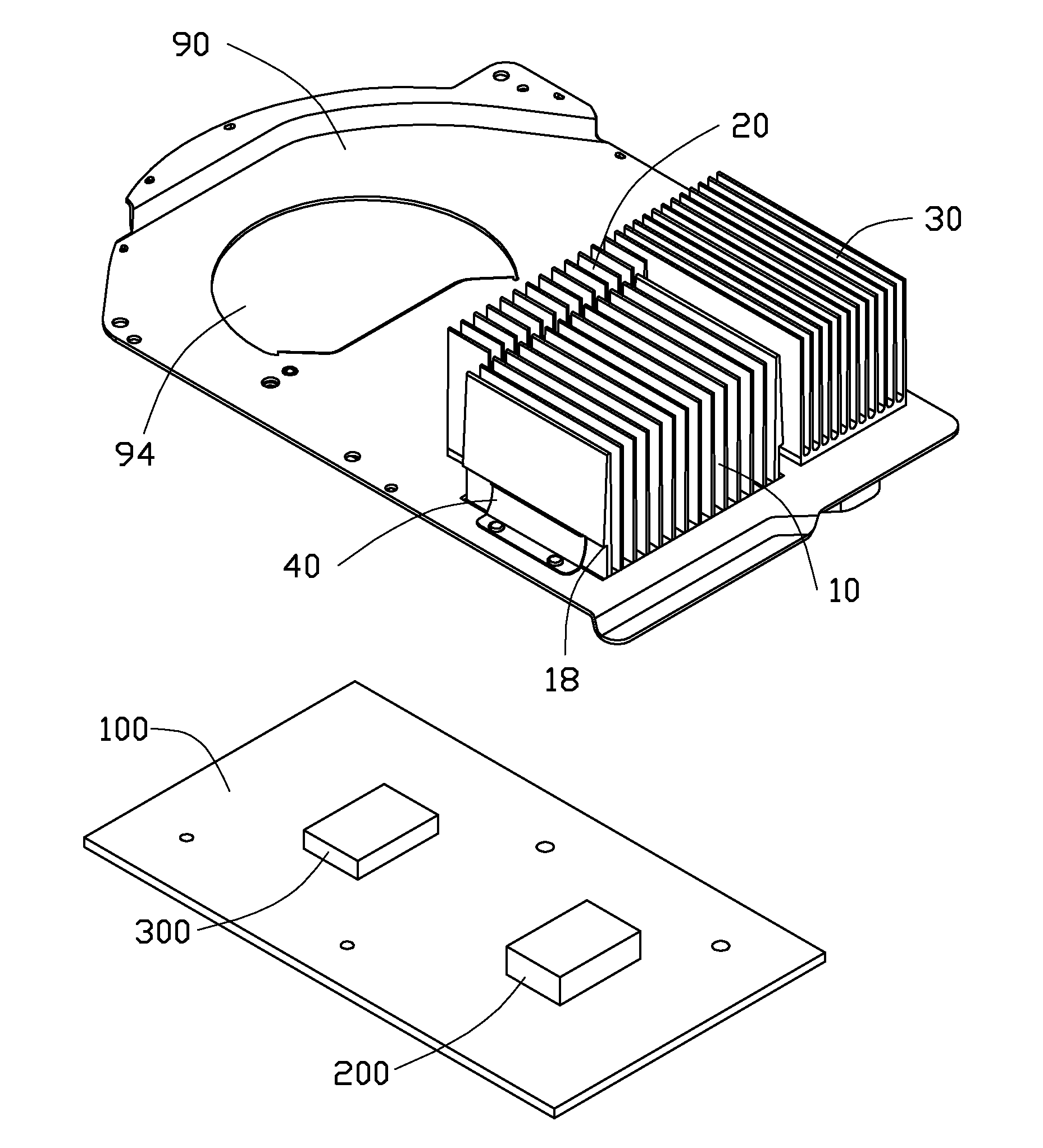
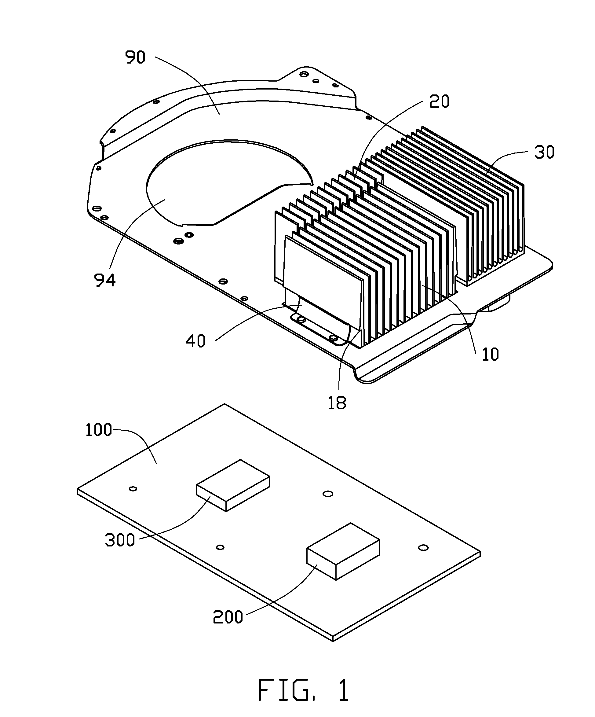
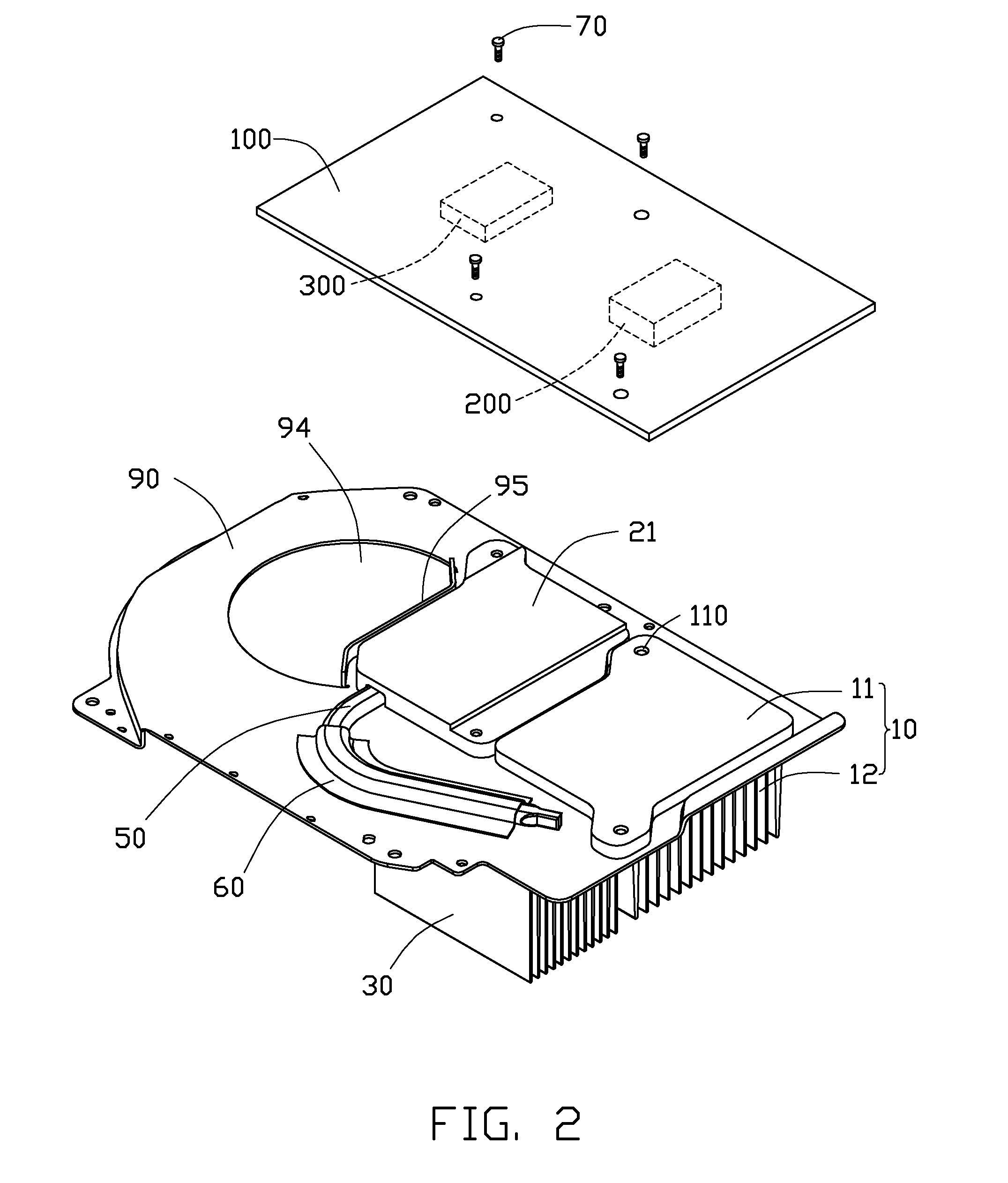
[0012]FIG. 1 illustrates a heat dissipation device in accordance with an embodiment of the present disclosure. The heat dissipation device thermally contacts a first electronic component 200 and a second electronic component 300 mounted on a printed circuit board (PCB) 100 of an electronic device (not shown), to dissipate heat generated by the first and second electronic components 200, 300. In this exemplary embodiment, the electronic device is a game player; the first electronic component 200 is a central processing unit (CPU), and the second electronic component 300 is a graphic processing unit (GPU).

[0013]The heat dissipation device comprises a connecting plate 90, a first heat sink 10, a second heat sink 20, and a third heat sink 30. The first, second and third heat sinks 10, 20, 30 are engaged on the connecting plate 90. The first heat sink 10 thermally contacts the first electronic component 200. The second heat sink 20 thermally contacts the second electronic component 300. ...


PUM


Abstract

A heat dissipation device is provided for dissipating heat generated by electronic components mounted on a printed circuit board in an electronic system. The electronic components have different heights. The heat dissipation device includes a connecting plate, at least two elastic members mounted on the connecting plate, and a heat sink having a substrate mounted on the connecting plate and located above one of the electronic components. A number of joining members extend through the printed circuit board and engage with the substrate to attach the substrate on the one electronic component on the printed circuit board. A distance between the substrate and the connecting plate is adjustable by adjusting the joining members to make the substrate intimately contact the one electronic component.

Description

BACKGROUND[0001]1. Technical Field[0002]The present disclosure relates to an electronic system with a heat dissipation device thermally contacting a plurality of electronic components having different heights, to dissipate heat of the electronic components simultaneously.[0003]2. Description of Related Art[0004]Generally, a heat dissipation device thermally contacts electronic components mounted on a printed circuit board (PCB) to dissipate heat of the electronic components. The heat dissipation device comprises a base contacting the electronic components, and a plurality of fins extending upwardly from a top surface of the base. When the electronic components have different heights, the base of the heat dissipation device is not able to intimately contact all of the electronic components. As a result, a large thermal barrier exists between some of the electronic components and the base, which adversely affects the heat dissipation for such electronic components.[0005]What is needed...

Claims


Application Information

Patent Timeline
Patent Type & Authority Patents(United States)
IPC IPC(8): H05K7/20G06F1/20
CPCH05K7/20154
Inventor CHEN, GUOZHOU, SHI-WENCHEN, CHUN-CHI
Owner FU ZHUN PRECISION IND SHENZHEN
Learn More