Imparted charge in situ pipelining device

a technology of in situ pipelining and charge, which is applied in the direction of spraying apparatus, coating, lighting and heating apparatus, etc., can solve the problems of unsatisfactory removal of pipes, and achieve the effect of increasing the build-up of pipes and low viscosity

Inactive Publication Date: 2011-08-09
QUEST INSPAR +2
View PDF16 Cites 15 Cited by
  • Summary
  • Abstract
  • Description
  • Claims
  • Application Information

AI Technical Summary

Benefits of technology

[0010]The lining material can be premixed an conveyed to the device through a heated, non-expanding hose. The heating maintains a low viscosity. The heated hose may be contained in an umbilical also conveying an electric cable, a CCTV cable and pressurized air hose. The umbilical may also contain an insulated chilled nitrogen hose. The nitrogen may be exhausted into the atomized pipe lining material to increase lining build up.

Problems solved by technology

Removal of pipes is unsatisfactory since it often creates dispersion of asbestos dust or lead paint.

Method used


Image

  • Imparted charge in situ pipelining device
  • Imparted charge in situ pipelining device
  • Imparted charge in situ pipelining device

Examples


Embodiment Construction

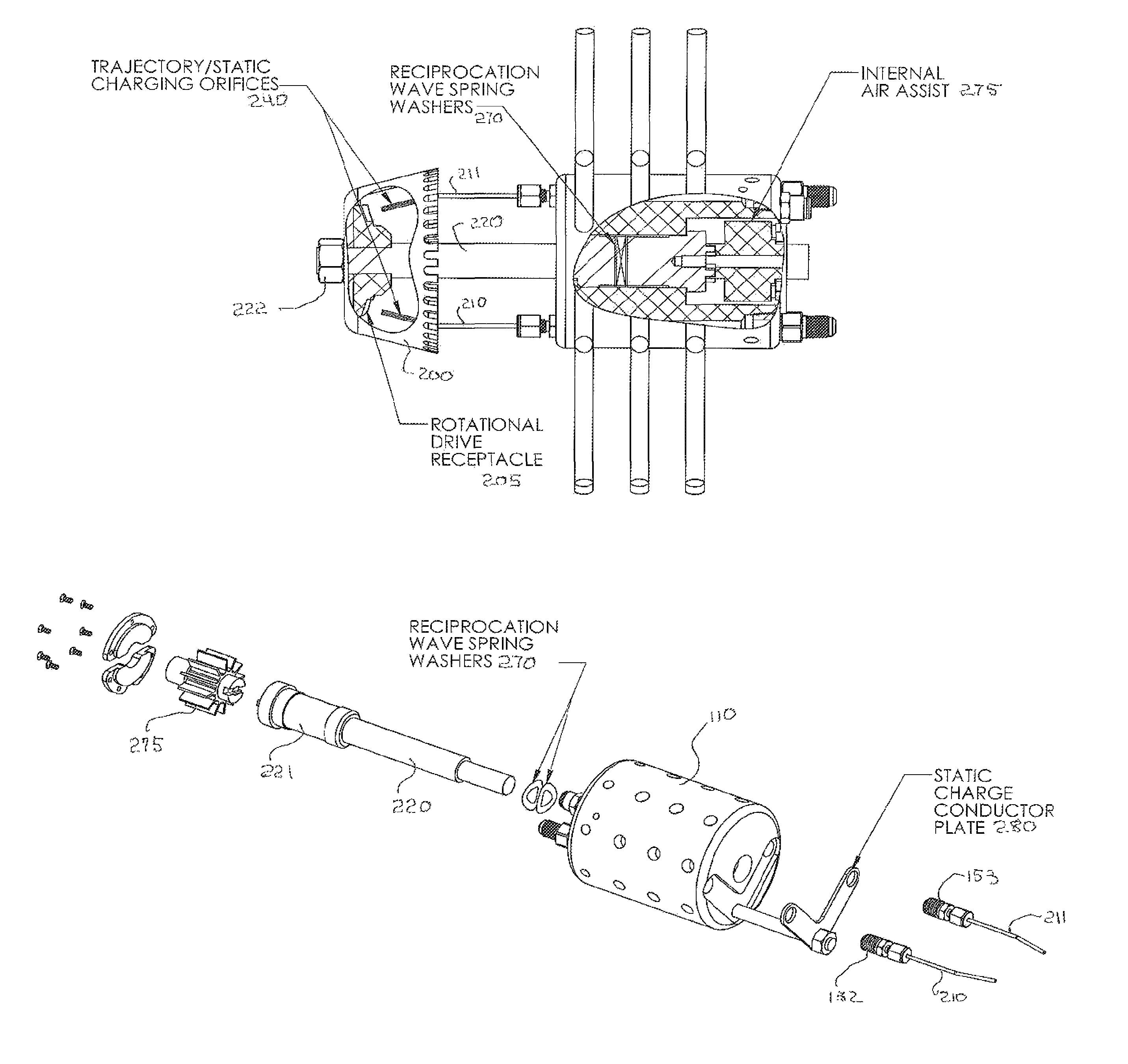
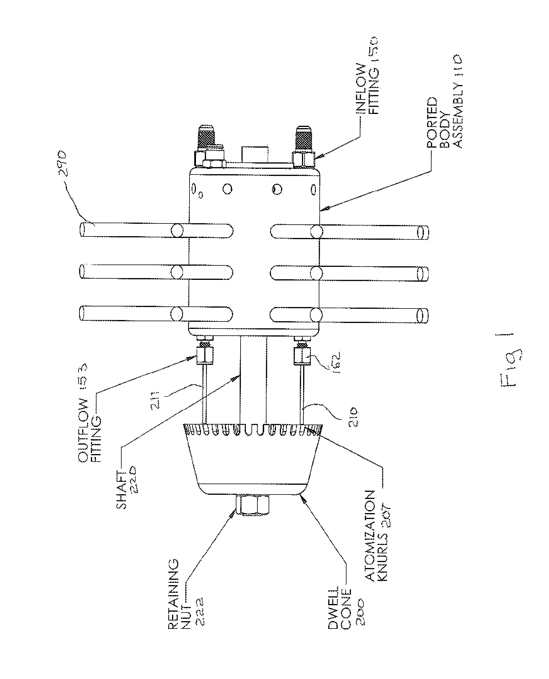
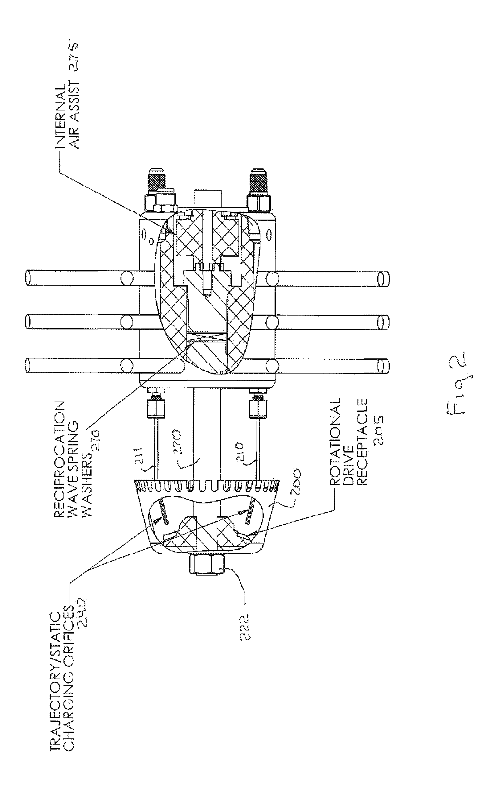
[0033]The invention pertains to a lining device that can be pulled through a pipe having an approximate diameter between 1 and 36 inches. The device is connected to an umbilical at a second ported assembly body. The umbilical conveys pipe lining material to the device. The lining hose within the umbilical is heated and non-expanding. This allows the lining to be mixed at a remote location and pumped under pressure to the dispenser apparatus. The second ported assembly body (“second housing”) conveys the lining mixture into two branches that are conveyed to a first front end of a first ported body assembly (“first housing”). The multi-part housing connected with flexible hose allows the apparatus to navigate tight turns in the pipe. The lining mixture passes over wave / pulse generation tabs mounted within the two lining annulus of the first housing.

[0034]Due to the small size of the apparatus having the ability to traverse 90° angle, the lining apparatus can be installed into the pipi...


PUM


Abstract

The invention pertains to a lining device that can be pulled through a pipe having an approximate diameter between 1 and 36 inches. The device sprays an electrically charged lining mixture 360° onto the inside pipe surface. The lining mixture is electro-statically charged to facilitate full encapsulation and adhesion to all pipe wall surfaces in a circumferentially uniform thickness. The lining device can be contained in a multipart housing having flexible rod-like components that hold the device in the center of the longitudinal axis of the pipe. The lining mixture is conveyed to the device through heated non expanding hose. The non expanding properties facilitate the delivery of the lining under pressure to the device. The device also incorporates a dwell cone having a knurled edge that atomizes the lining mixture as it is centrifugally thrown onto the pipe wall. The device may further incorporate nitrogen in mixing the lining material.

Description

RELATED APPLICATIONS[0001]This application incorporates by reference herein Ser. No. 12 / 611,305, entitled “Apparatus and Method for Lining Large Diameter Pipe with an Environmentally Compatible Impervious Membrane” filed Nov. 3, 2009, and now U.S. Pat. No. 7,726,256. This application also incorporates “Method and Apparatus for Lining Pipes with Environmentally Compatible Impervious Membrane” by reference, Ser. No. 12 / 476,983 filed Jan. 2, 2009 and now U.S. Pat. No. 7,591,901.BACKGROUND OF INVENTION[0002]1. Field of Invention[0003]This disclosure pertains to the distribution of drinking water within existing piping systems in buildings and structures. With general infrastructure within the US and around the world in a precarious state of decay it has been the object of many to provide for a cost effective method to perform in situ-rehabilitation of these properties. In the global arena, water distribution systems are seriously compromised with failures creating community disturbances...

Claims


Application Information

Patent Timeline
Patent Type & Authority Patents(United States)
IPC IPC(8): B05B5/025B05B3/00B05B13/06
CPCB05B1/005B05B5/001B05B13/0636B05B5/12B05B5/1608B05B5/0411B05B12/004B05B5/0415
Inventor WEISENBERG, KENTPRIMEAUX, II, DUDLEY
Owner QUEST INSPAR
Why Eureka
Try Eureka