Connecting terminal for printed circuit boards

a technology of connecting terminals and printed circuit boards, applied in the direction of coupling contact members, coupling device connections, contact members penetrating/cutting insulation/cable strands, etc., can solve the problem of fundamentally unsuitable connection terminals for printed circuit board technology, and the characteristic lever opener cannot be used to quickly disconnect individual terminal connections, etc. problem, to achieve the effect of reducing the installation height of the insulating housing, simple assembly, and simple sectional geometry

Inactive Publication Date: 2011-08-09
PHOENIX CONTACT GMBH & CO KG
View PDF14 Cites 21 Cited by
  • Summary
  • Abstract
  • Description
  • Claims
  • Application Information

AI Technical Summary

Benefits of technology

[0007]It is, therefore, an objective of the invention to provide a connecting terminal of the kind mentioned above, which avoids the disadvantages of the known arrangements of the state-of-the-art as mentioned above and to provide a technical solution that enables the manufacture of a connecting terminal with a simple functional design and small installation size, which can be customized easily and quickly, and where the clamping contact occurs independent of the insulating housing, for the printed circuit board connection.
[0015]In order to manufacture a connecting terminal with these features of the present invention in spring force technology for a quick, reliable and universal clamping connection in a miniaturized design, taking into account the wiring requirements of the device manufacturers and printed circuit board processors, it is recommended, according to the invention, to produce a plug-type connector that, on the one hand, reliably ensures an optimal electrical contact and, on the other hand, allows for a reduction in the installation size. Plug-type connectors are characterized by space-saving designs, quick connection technology due to the spring force and have no locking mechanism between plug and base or pin strip. The universal usability of the connecting terminals relates to both vertical and horizontal plug directions of the plug-type connector in connection with the base strip and the electrical conductors to be connected with them to the printed circuit board.
[0017]The main objectives are the reduction of the installation size of the insulating housing and the manufacture of simple components that can be customized easily and quickly.
[0019]According to the invention, these objectives are solved by the development of a plug-type connector that ensures the advantages of the spring force technology and the advantages of the high clamping reliability through a reliable mechanical connection and a reliable electrical contact combined with the continued miniaturization of the assembly in order to increase at the same time the component density on the printed circuit board.
[0021]According to the invention, after punching out numerous end pieces, preferably five end pieces are formed at the strip material. The strip material has the task to, on the one side, serve as a bus bar and provide an optimal contact surface for the electrical conductor to be connected, and, on the other side, to form, for example in the base strip, from the end pieces a contact element serving as a socket contact for connecting a contact pin. According to the invention, additional end pieces serve as a means of attachment for the spring force element with the end pieces as the means of attachment forming a u-shaped spring cage. The u-shaped spring cage exhibits two retaining clips that include openings for receiving the retaining means of the spring force element, whereby the retaining means of the spring force element consist of protrusions that engage in the openings of the retaining clips of the spring cage. The u-shaped spring cage is pre-stressed such that it rests against the contact surfaces of the leg spring without an installation gap. The assembly assembled in this manner provides sufficient stability for installation in the associated insulating housing without the need for additional measures. The deflection of the spring force element occurs upon insertion of a sufficiently bend-resistant electrical conductor and / or by using an actuation means, preferably a spring push element that can be operated using a commercial actuation tool and that is located in the insulating housing. The spring force element can also be formed from a set of springs with the set of springs being comprised of individual leg springs. According to the invention, this advantage is made possible by the different sizes of the openings in the retaining clips of the contact insert. The embodiment of the contact insert subject to the invention with symmetrical mounting of the spring force elements, the spring force element designed according to the invention with simple sectional geometry and its simple assembly together with the advantageous connection with the contact insert result in a closed terminal cage, which makes it possible to reduce the installation height of the insulating housing significantly. Thus, the insulating housing made of a thermoplastic material by injection molding can be adapted optimally in its design to the electrical insulating properties.

Problems solved by technology

Although this known arrangement is provided for several terminal points, it is fundamentally not suitable as a connecting terminal for printed circuit board technology.
The disadvantage is that a quick disconnect of the individual terminal connections is not provided by the characteristic lever opener.

Method used


Image

  • Connecting terminal for printed circuit boards
  • Connecting terminal for printed circuit boards
  • Connecting terminal for printed circuit boards

Examples


Embodiment Construction

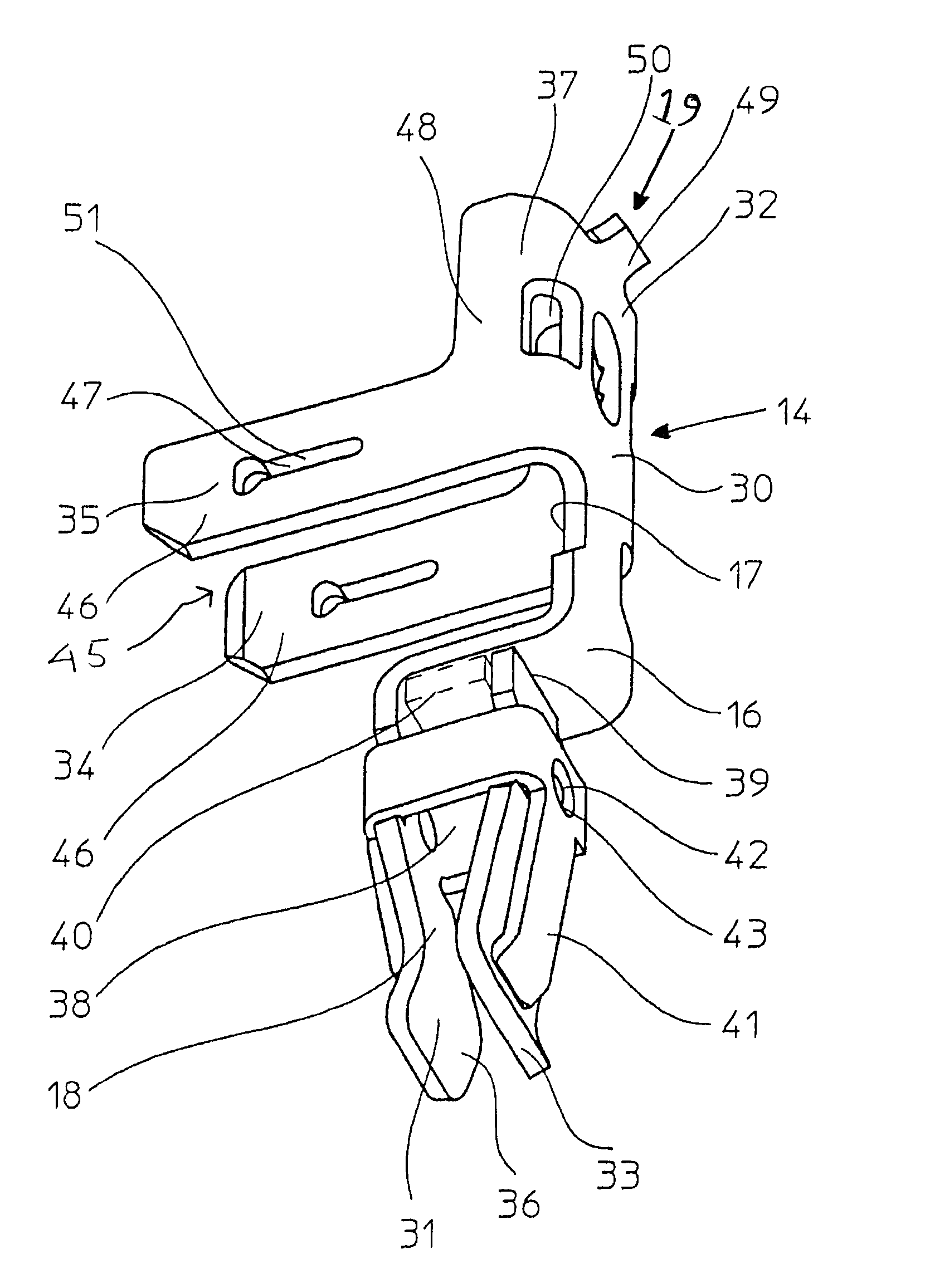
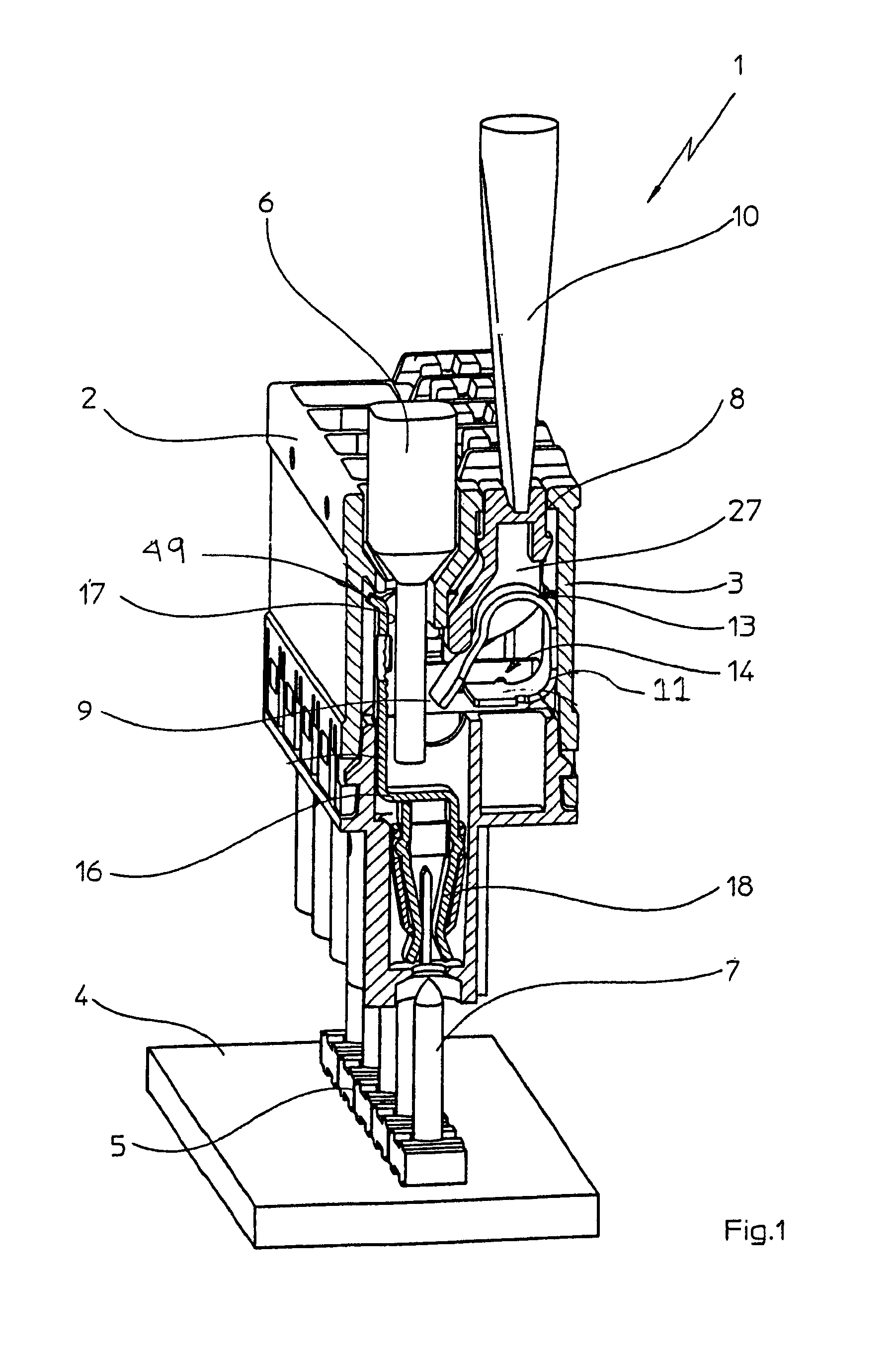
[0026]FIG. 1 presents in a perspective sectional view of an advantageous embodiment of the connecting terminal 1 according to the invention in a complete form according to the type-defining kind of a plug-type connector 2 in a miniaturized embodiment of the insulating housing 3 in block design, where said embodiment can be plugged onto a printed circuit board 4 with a mounted base strip 5, with the base strip 5 exhibiting a pole number of two to twelve, and being mounted either in a vertical or horizontal plug-in direction in relation to the printed circuit board utilizing, for example, a through hole reflow solder method as is well known in the art.

[0027]The connecting terminal 1 consists of an insulating housing 3, where the insulating housing 3 in block design is divided into two housing sections, an upper and a lower section, and forms a receiving space 27. The receiving space 27 includes at least one actuation means 8, preferably a push element made of plastic, for opening the ...


PUM


Abstract

A contact insert for a connecting terminal of a multiplicity of mutually isolated connection elements, designed in particular for printed circuit boards, with a spring force element being mounted symmetrically, with the spring force element designed with a simple section geometry and its simple mounting together with the advantageous connection to the contact insert, results in a closed terminal cage which makes it possible to reduce the physical height of the dielectric housing to a major The connecting terminal is used as a linking element in printed circuit board connection technology for providing a reliable supply to industrial electronics and economic individual wiring on printed circuits.

Description

TECHNICAL FIELD[0001]The present invention relates in general to the field of electrically conductive physical connections and more particularly, to a connector providing a physical connection of a multiplicity of mutually isolated connection elements, designed in particular for printed circuits, with the physical connections representing a component of an electrical connection between two or more conductive elements, using a spring.BACKGROUND INFORMATION[0002]As is known from the state-of-the-art, connecting terminals, in particular a plug-type connector for electrical contacting and for attachment to a printed circuit board equipped with a base strip or electrical equipment or the like, for at least one electrical conductor, are available in many designs, for example in single-pole or multi-pole designs, with a housing made of insulating material either in block or modular design, where the housing made of insulating material exhibits at least one insertion opening for inserting a...

Claims


Application Information

Patent Timeline
Patent Type & Authority Patents(United States)
IPC IPC(8): H01R4/26
CPCH01R4/4836H01R9/091H01R13/115H01R13/17H01R12/778H01R13/18H01R4/48365
Inventor HOLSTE, DIETER
Owner PHOENIX CONTACT GMBH & CO KG
Why Eureka
Try Eureka