
Chemical mechanical polishing pad having improved groove pattern

a technology of mechanical polishing and groove pattern, which is applied in the field of mechanical and chemical polishing apparatus, can solve the problems of excess metal on the center and metal remaining on the product wafer, and achieve the effects of greater mechanical and chemical polishing, greater surface area, and greater friction

Active Publication Date: 2011-08-23
TEXAS INSTR INC
View PDF23 Cites 3 Cited by
  • Summary
  • Abstract
  • Description
  • Claims
  • Application Information

AI Technical Summary

Benefits of technology

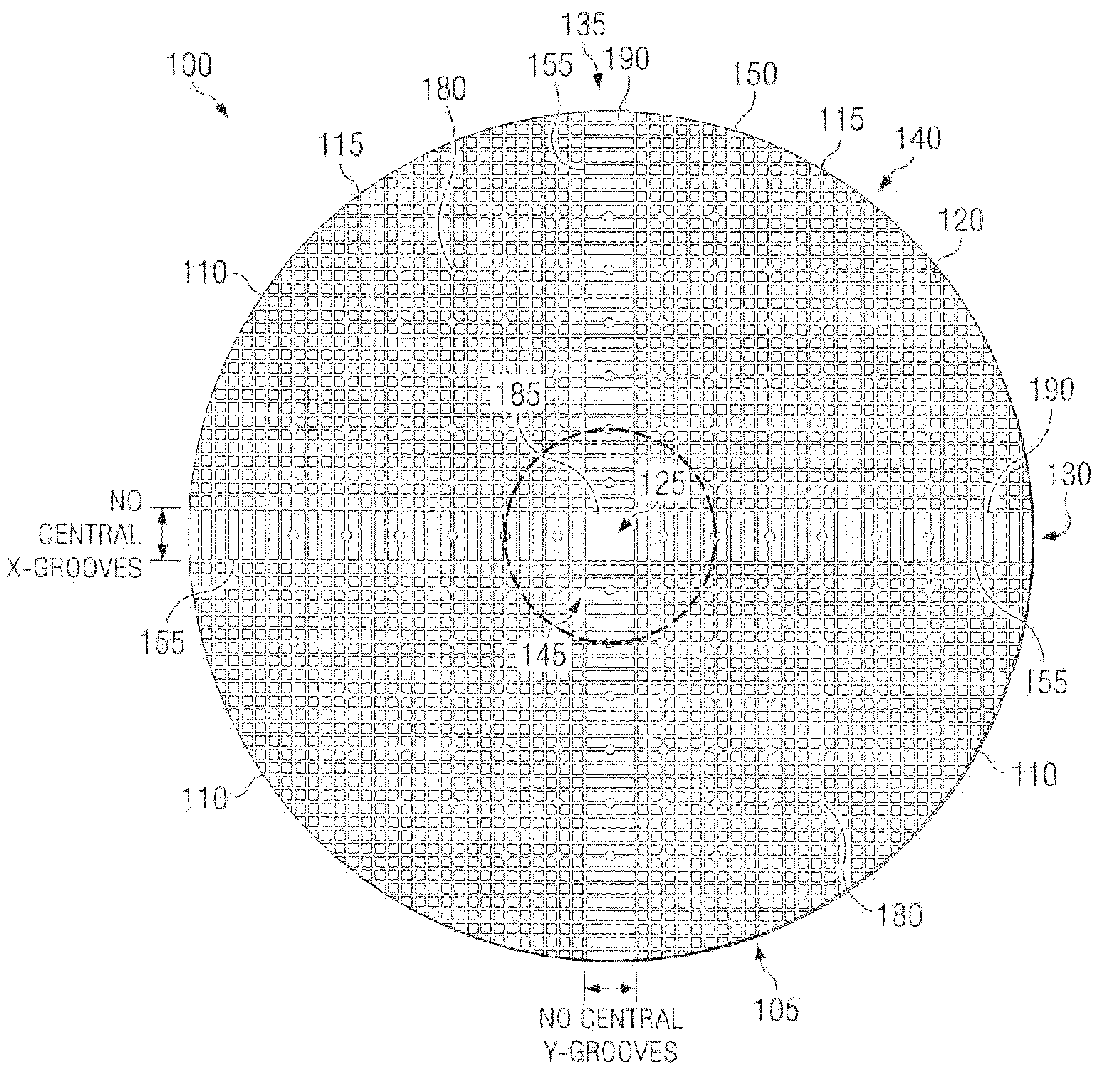
[0008]The one or more second mesas, for example, are associated with a center region of the polishing pad, wherein the second surface area is at least twice the first surface area. Thus, the one or more second mesas associated with the center region of the polishing pad provide a greater mechanical and chemical polishing to a wafer than polishing pads of the prior art, since the greater surface area provides a greater amount of friction between the polishing pad and the wafer, as well as decreasing corners that may be worn during conditioning of the polishing pad.

Problems solved by technology

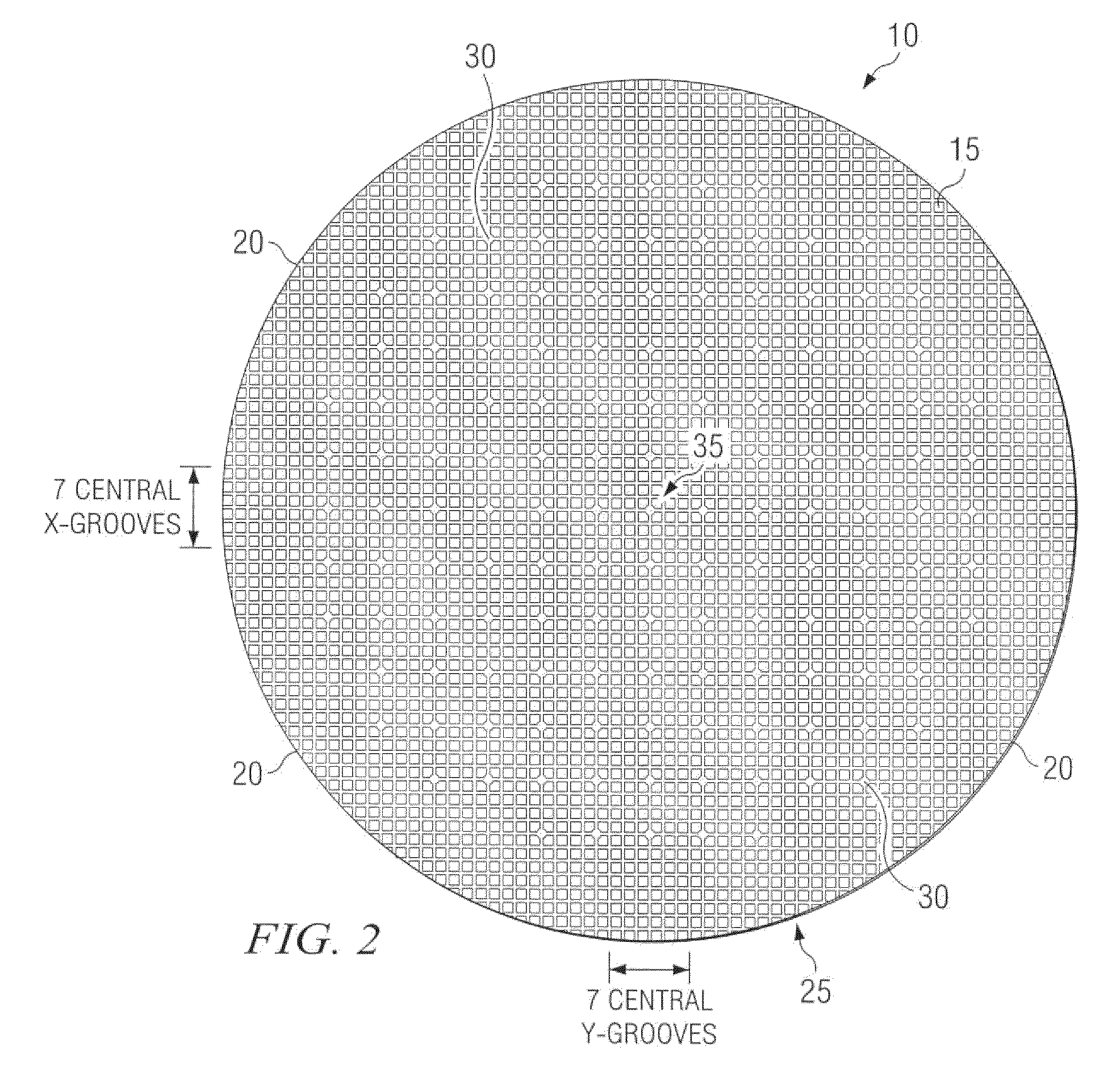
One problem conventionally seen in CMP processing involves metals remaining on product wafers after the CMP process is performed.
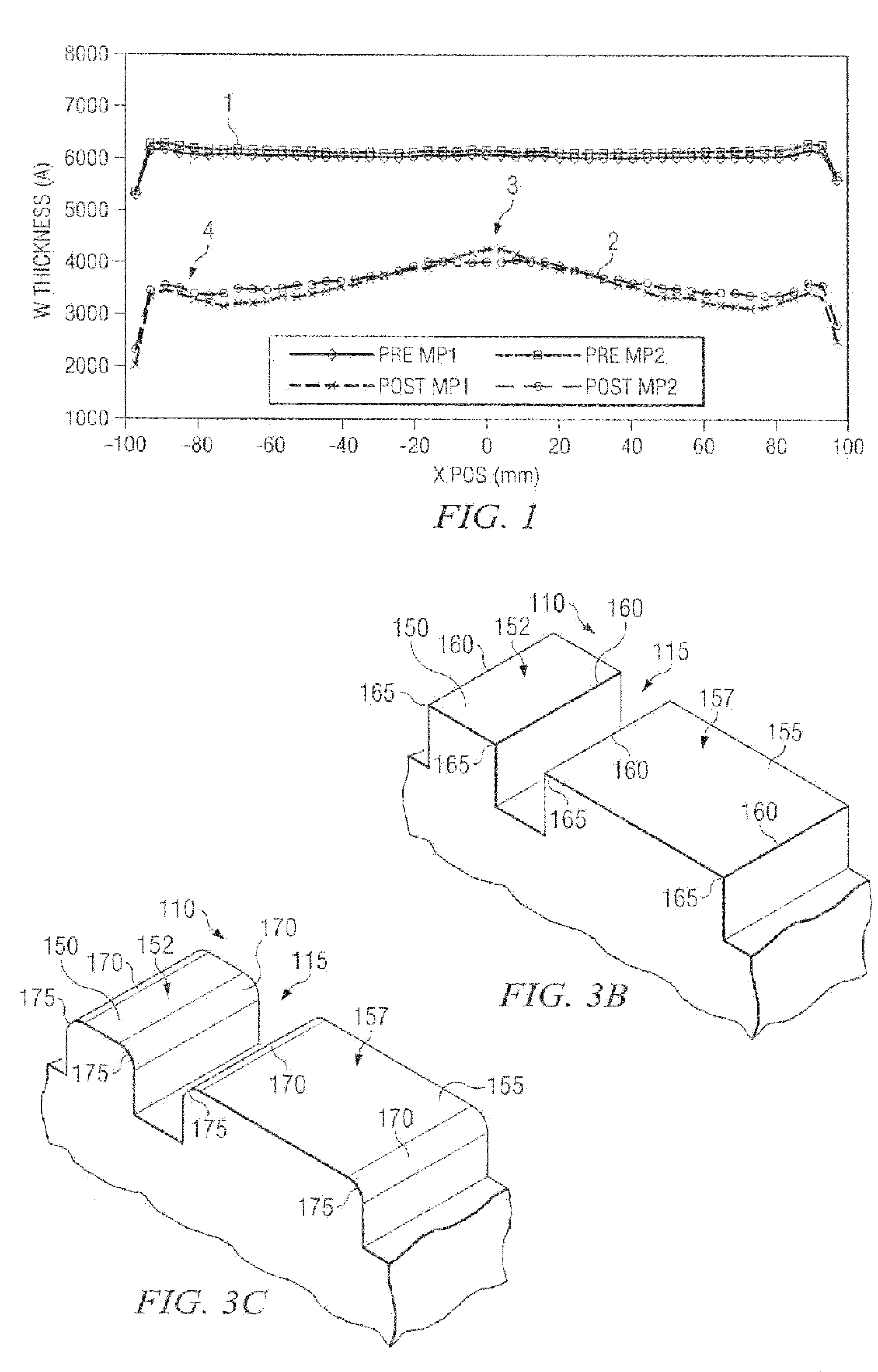
In an orbiting CMP apparatus, excess metal can remain on a center of the wafer after the CMP process is complete due to a slow removal rate associated with a center of the conventional polishing pad.

Method used


Image

  • Chemical mechanical polishing pad having improved groove pattern
  • Chemical mechanical polishing pad having improved groove pattern
  • Chemical mechanical polishing pad having improved groove pattern

Examples


Embodiment Construction

[0017]The present invention is directed towards chemical-mechanical polishing (CMP) of a workpiece, wherein defects are generally mitigated. Accordingly, the present invention will now be described with reference to the drawings, wherein like reference numerals are used to refer to like elements throughout. It should be understood that the description of these aspects are merely illustrative and that they should not be taken in a limiting sense. In the following description, for purposes of explanation, numerous specific details are set forth in order to provide a thorough understanding of the present invention. It will be evident to one skilled in the art, however, that the present invention may be practiced without these specific details.

[0018]In a tungsten CMP process, for example, a tungsten layer is formed over a wafer, wherein the tungsten generally “overfills” grooves or plugs that have been etched on a surface of a dielectric layer of the wafer, thus defining an overburden o...


PUM


Abstract

A chemical mechanical polishing pad and method for chemical-mechanical polishing is provided, wherein the polishing pad has a plurality of first mesas and one or more second mesas defined on a surface thereof. The plurality of first mesas are generally distributed about the surface of the polishing pad, wherein each of the plurality of first mesas has a first surface area associated therewith. The one or more second mesas are associated with a center region of the polishing pad, wherein each of the one or more second mesas has a second surface area associated therewith. The second surface area is at least twice the first surface area.

Description

RELATED APPLICATION[0001]This application claims priority to Ser. No. 60 / 877,301 filed Dec. 27, 2006, which is entitled “Chemical Mechanical Polishing Pad Having Improved Groove Pattern”.FIELD OF THE INVENTION[0002]The present invention relates generally to semiconductor processing, and more particularly to a chemical-mechanical polishing (“CMP”) apparatus for polishing a workpiece. Specifically, the present invention relates to an improved groove pattern for a CMP pad.BACKGROUND OF THE INVENTION[0003]Chemical-mechanical processing of a semiconductor wafer or substrate may include forming a dielectric layer over the semiconductor substrate, etching a plurality of trenches into the dielectric layer, and forming a metal layer, such as a tungsten layer, over the dielectric layer and the trenches, wherein the trenches are generally filled by the metal layer. A portion of the metal layer may be further removed via an abrasive polishing pad of a chemical-mechanical polishing (CMP) apparat...

Claims


Application Information

Patent Timeline
Patent Type & Authority Patents(United States)
IPC IPC(8): B24D11/00
CPCB24B37/26
Inventor HE, YANGHUACHEN, JINGQIULENG, YAOJIAN
Owner TEXAS INSTR INC
Learn More