Pitch-only densification of carbon-carbon composite materials

a carbon-carbon composite material and composite material technology, applied in the field of carbon-carbon composite material manufacturing, can solve the problems of low final densities, low final density, and long cycle time (typically about 5 cycles), and achieve the effects of reducing the density, reducing the cost of carbon-carbon composite manufacturing, and improving the quality of carbon-carbon composite materials

Active Publication Date: 2011-08-23
HONEYWELL INT INC
View PDF10 Cites 1 Cited by
  • Summary
  • Abstract
  • Description
  • Claims
  • Application Information

AI Technical Summary

Benefits of technology

[0008]The present invention overcomes problems inherent in lower density carbon-carbon composites—such as inferior thermal and mechanical properties, the potential for antioxidant migration away from the non-friction surfaces of the composite, and higher wear rates—by employing high carbon-yielding pitches to densify the carbon-carbon composites to a density of approximately 1.8 g / cc or greater. The high carbon yielding pitches which may be used in accordance with the present invention may include isotropic pitches, 100% anisotropic (mesophase) pitches, or mixtures of the two. They may be derived from petroleum, coal tar, or synthetic feedstocks. One advantage of using the mesophase pitches is the uniformity of composition that they impart to the composites, which results in reduced variation in C—C composites properties and performance.

Problems solved by technology

Unfortunately, this CVI process is expensive, capital intensive and is a time-consuming process, frequently taking several months to complete.
The problem with using these densification processes is the length of cycle time (typically about 5 cycles) and low final densities (often less than or less than 1.75 g / cc.
Also, coal tar pitch feedstocks exhibit high variability in properties and composition that may cause variation in the properties and performance of the carbon-carbon composite.

Method used


Image

  • Pitch-only densification of carbon-carbon composite materials
  • Pitch-only densification of carbon-carbon composite materials

Examples


examples

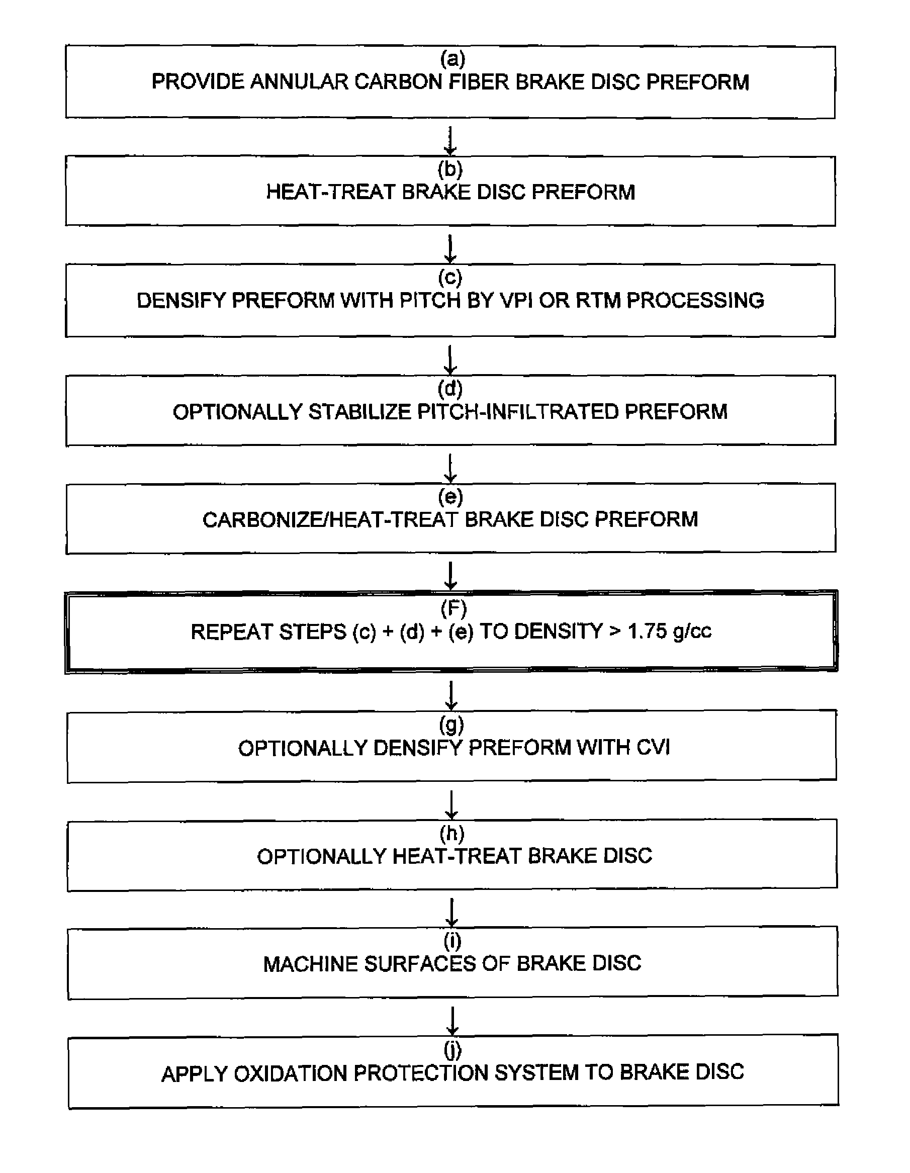
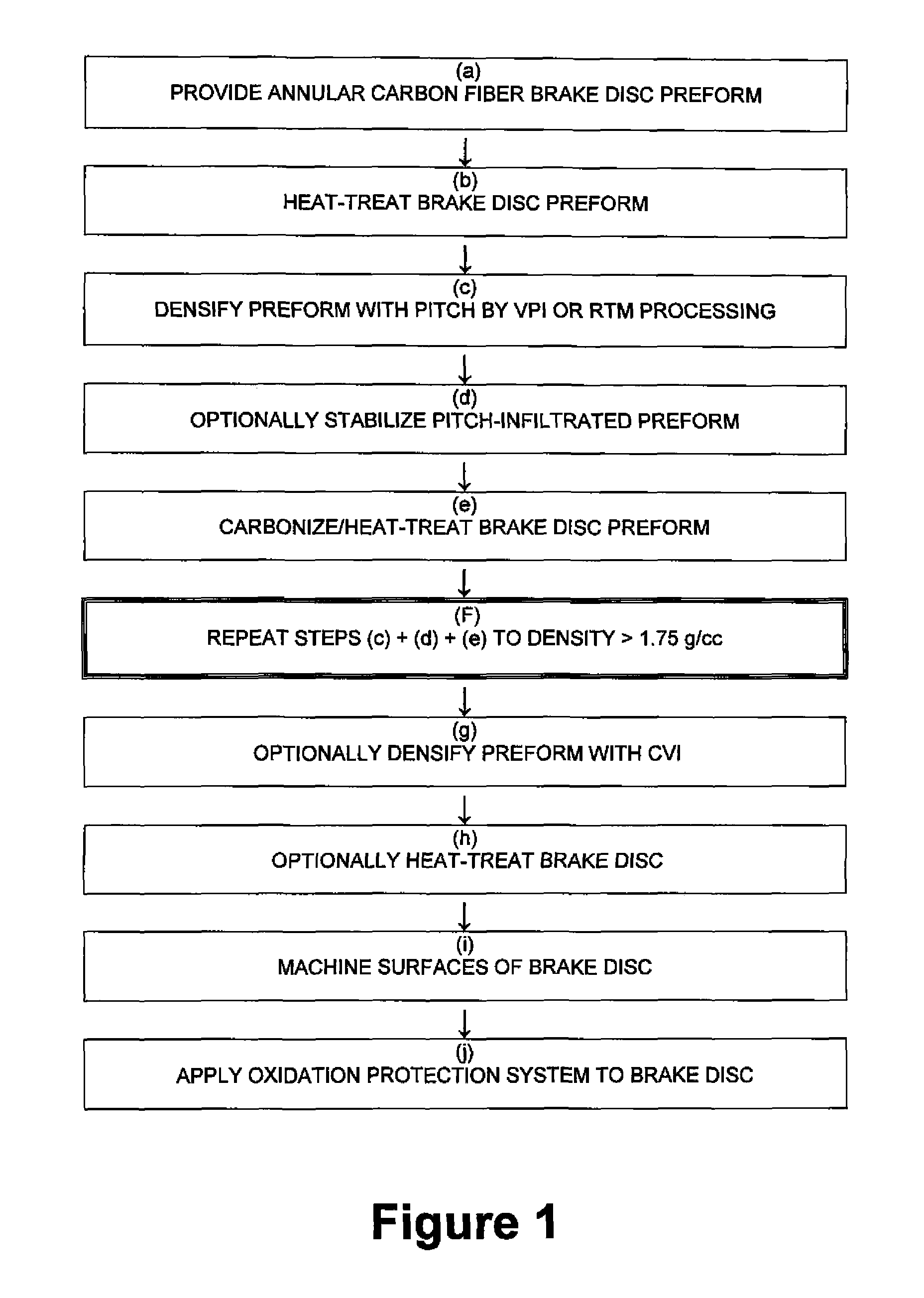
Specific embodiments of the present invention may employ the following densification cycles

[0034](1) Pitch-Only Densification:[0035]Fabricating a carbon fiber preform,[0036]heat-treating the carbon fiber preform at 1400-2540° C.,[0037]infiltrating the carbon fiber preform with a high carbon-yielding pitch using VPI (vacuum pressure infiltration) or resin transfer molding (RTM) process,[0038]optionally stabilize the high char-yielding pitch-infiltrated preform,[0039]repeating the infiltration step and optionally the stabilization step to achieve a final density of >1.75 g / cc (and usually above 1.8 g / cc),[0040]heat-treating the preform at 1400-2000° C., machining the surfaces of the preform, and[0041]applying an oxidation protection system.

[0042](2) Densification with Pitch and CVI / CVD:[0043]Fabricating a carbon fiber preform,[0044]heat-treating the carbon fiber preform at 1400-2540° C.,[0045]infiltrating the carbon fiber preform with a high carbon-yielding pitch using VPI (vacuum pre...


PUM

PropertyMeasurementUnit
temperatureaaaaaaaaaa
densityaaaaaaaaaa
densityaaaaaaaaaa

Abstract

Method for making carbon-carbon composite friction product, by: fabricating carbon fiber preform; heat-treating the carbon fiber preform; infiltrating the carbon fiber preform with a high carbon-yielding pitch using VPI (vacuum pressure infiltration) or resin transfer molding (RTM) processing; carbonizing the preform with an intermediate heat-treatment at 800-2000° C.; repeating the pitch infiltration and carbonization steps to achieve a final density of >1.75 g / cc; machining the surfaces of the preform; and applying an oxidation protection system. This approach overcomes problems inherent in lower density carbon-carbon composites by employing high carbon-yielding pitches to densify the carbon-carbon composites to a high density. The high carbon yielding pitches may include isotropic pitches, 100% anisotropic (mesophase) pitches, or mixtures of the two. They may be derived from petroleum, coal tar, or synthetic feedstocks.

Description

FIELD OF THE INVENTION[0001]This invention relates to the manufacture of carbon-carbon composite materials, and especially to the manufacture of aircraft brake discs made of improved carbon-carbon composite materials.BACKGROUND OF THE INVENTION[0002]The brake discs of most wide-body commercial and military aircraft are made from Carbon-Carbon (C—C) composites. Traditionally, C—C composites used as friction materials are produced by combining carbon fibers with a carbon matrix material that is deposited around the fibers using a Chemical Vapor Infiltration (CVI) process.[0003]Unfortunately, this CVI process is expensive, capital intensive and is a time-consuming process, frequently taking several months to complete. Therefore, several attempts have been made to reduce the cycle time and costs associated with CVI processing by using lower cost pitches together with VPI and RTM processes. The problem with using these densification processes is the length of cycle time (typically about ...

Claims


Application Information

Patent Timeline
Patent Type & Authority Patents(United States)
IPC IPC(8): C01B31/00
CPCC04B35/83F16D69/023C04B2235/5268C04B2235/614C04B2235/616C04B2235/656C04B2235/77
Inventor LA FOREST, MARKMURDIE, NEILCOLE, DAVID R.
Owner HONEYWELL INT INC
Why Eureka
Try Eureka