Motor

a motor and motor technology, applied in the field of motors, can solve the problems of difficult to properly control the phase difference of the first and second rotors only by the action of centrifugal force, and the inability to properly control the phase difference of the first and second rotors with proper timing, etc., to achieve the maximum value of torque output of the motor, increase the amount of interlinking magnetic fields, and increase the effect of field flux

Inactive Publication Date: 2011-08-23
HONDA MOTOR CO LTD
View PDF13 Cites 5 Cited by
  • Summary
  • Abstract
  • Description
  • Claims
  • Application Information

AI Technical Summary

Benefits of technology

[0026]According to the motor of the present invention, the permanent magnets are arranged in the peripheral direction in the inner rotor and the outer rotor. Thereby, for example, the amount of interlinking magnetic fields that the field fluxes generated by the permanent magnets of the outer rotor interlink the stator windings can be efficiently increased or reduced by the field fluxes generated by the permanent magnets of the inner rotor. Also, in the field-strengthening state, the torque constant (that is, torque / phase current) of the motor can be set to a relatively high value. In addition the maximum value of the torque output by the motor can be increased without reducing a current loss during the operation of the motor or without changing the maximum value of the output current of an inverter which controls to supply with a current to the stator windings.
[0027]Moreover, the rotating mechanism supplies a working fluid to the pressure chambers which are defined inside the inner rotor by the first member integrally and rotatably provided with respect to the outer rotor and by the second member integrally and rotatably provided with respect to the inner rotor, thereby changing the relative phase between the inner rotor and the outer rotor. Therefore, it is possible to make an induced voltage constant to be variable easily and properly and with desired timing while suppressing complication of the motor. As a result, it is possible to expand an operational rotational frequency range and torque range, improve operating efficiency, and expand an operational range at high efficiency. Moreover, the relative phase between the inner rotor and the outer rotor can be set to a desired phase by controlling the amount of supply of the working fluid to the pressure chambers. In addition, since the first member and the second member define the pressure chambers inside the inner rotor, particularly an increase in axial thickness of the motor can be suppressed, and the motor can be miniaturized.
[0013]A configuration in which the working fluid is supplied to the pressure chambers via the vane rotor may be adopted.
[0014]A configuration in which the first member is end plates which are integrally provided in the outer rotor and the rotating shaft so as to cover both end surfaces of the inner rotor and the outer rotor, and which transmits torque to the rotating shaft; and the second member is a ring gear which is arranged between the inner rotor and the rotating shaft, is connected with the inner rotor and the rotating shaft by helical splines, defines the pressure chambers with the drive plates, and is moved axially by supply of the working fluid to the pressure chambers may be adopted.

Problems solved by technology

Meanwhile, in the motor related to an example of the above conventional technique, for example, in a case where the phase difference of the first and second rotors is controlled according to the rotational speed of the motor, there occurs a problem that the phase difference of the first and second rotors can be controlled only in the operating state of the motor, i.e., only in a state where the centrifugal force according to the rotational speed of the motor acts, and the phase difference cannot be controlled with proper timing including a stopped state of the motor.
Further, in a state where the vibration from the outside is apt to act on the motor like a case where the motor is mounted on a vehicle as a driving source, there occurs a problem that it is difficult to properly control the phase difference of the first and second rotors only by the action of a centrifugal force.
Therefore, there occurs a problem that the control processing of the motor may be complicated.

Method used


Image

  • Motor
  • Motor
  • Motor

Examples


first embodiment

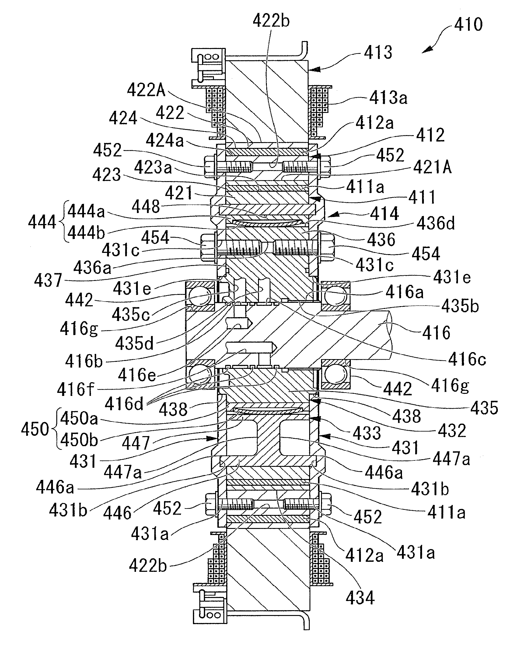
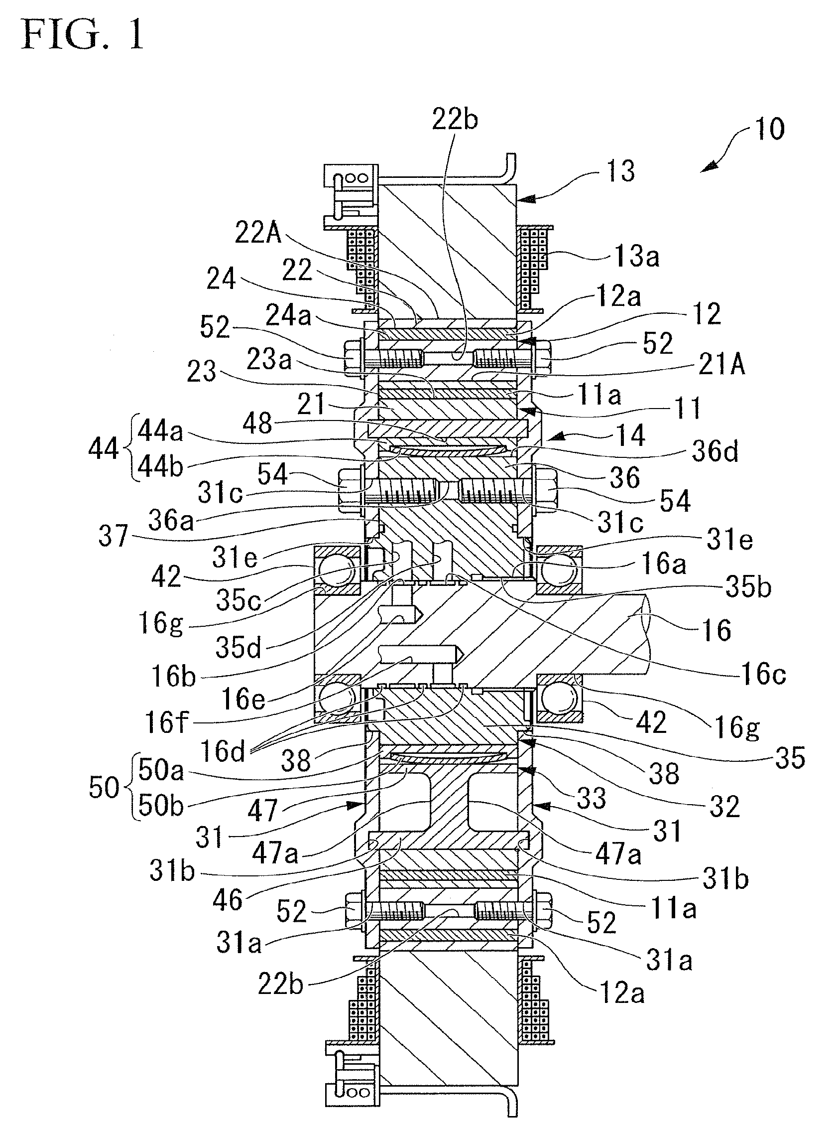
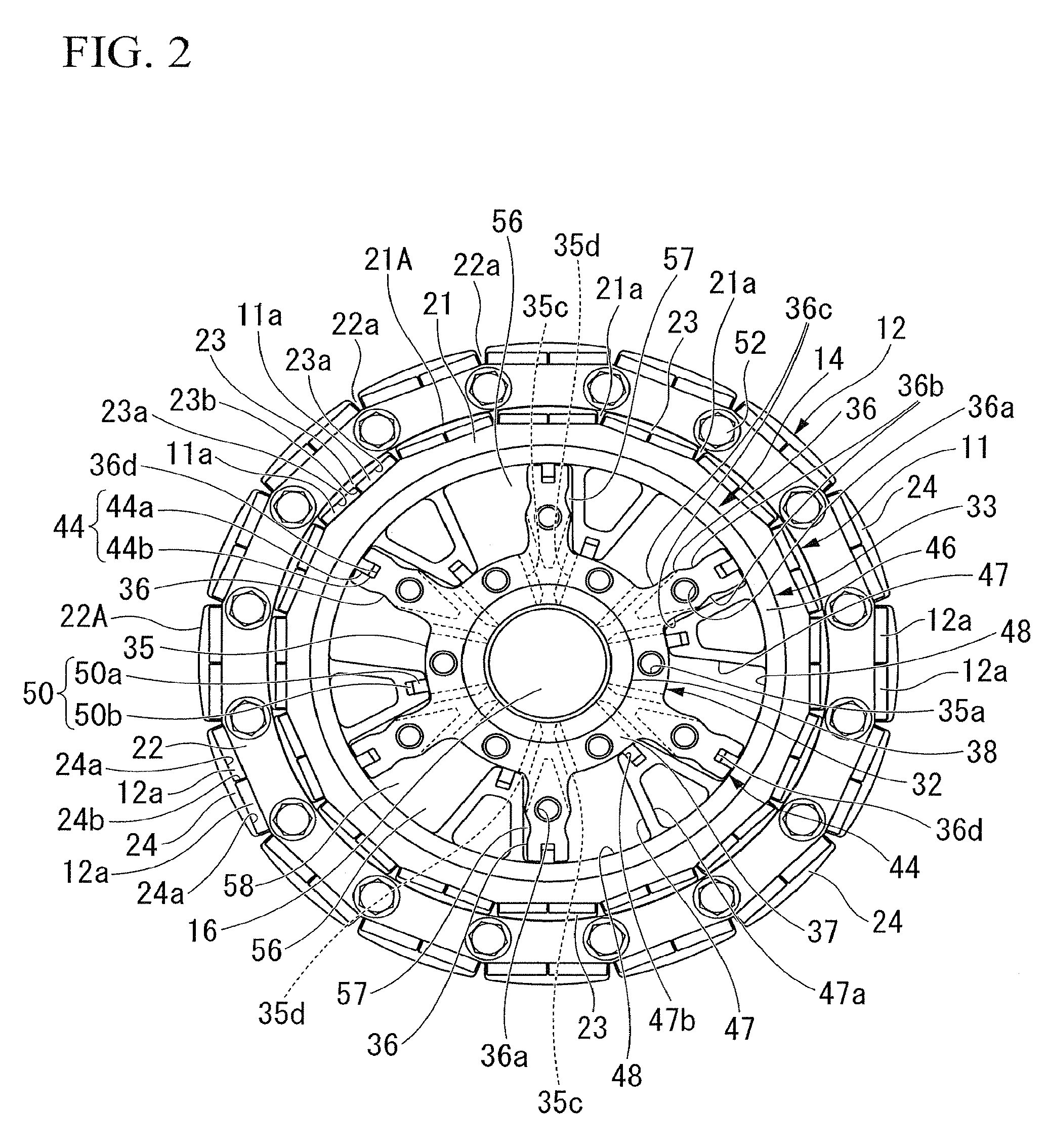
[0167]Hereinafter, a motor according to a first embodiment of the present invention is described, referring to FIG. 1 to FIG. 10B. As shown in FIGS. 1 to 3, the motor 10 according to this embodiment is a brushless DC motor including a substantially annular inner rotor 11 which is rotatably provided about the axis of rotation of the motor 10, a substantially annular outer rotor 12 which is rotatably provided about the same axis of rotation radially outside the inner rotor 11 and which is provided so as to be matched with the inner rotor in position in the direction of the axis of rotation, a stator 13 which has a plurality of phases of stator windings 13a, shown in FIG. 1, which generate a rotating magnetic field which rotate the inner rotor 11 and the outer rotor 12, a rotating mechanism (rotating device) 14 which is connected to the inner rotor 11 and the outer rotor 12, and changes the relative phase between the inner rotor 11 and the outer rotor 12 with the hydraulic pressure (fl...

second embodiment

[0209]Next, for a motor according to a second embodiment of the invention, different portions from the above first embodiment are described mainly with reference to FIGS. 11 and 12. In addition, the same reference numerals are given to the same portions as the above first embodiment, and the description thereof is omitted.

[0210]In this embodiment, a portion of the rotating mechanism 14 in the above first embodiment is altered. First, as shown in FIG. 11, one drive plate 31, similarly to the above first embodiment, is fixed to the outer rotor 12 with by the bolts 52, . . . , and 52, is fixed to the boss 35 of the vane rotor 32 by bolts (not shown), and is fixed to the impeller portions 36 of the vane rotor 32 by the bolts 54.

[0211]On the other hand, an annular drive plate 61 is arranged axially opposite the drive plate 31 so as to cover the outer rotor 12 and an outer peripheral portion of an inner rotor 76. In the drive plate 61, bolt insertion holes 61a, . . . , and 61a which pass ...

third embodiment

[0216]Next, for a motor according to a third embodiment of the invention, different portions from the above first embodiment are described mainly with reference to FIG. 13. In addition, the same reference numerals are given to the same portions as the above first embodiment, and the description thereof will be omitted.

[0217]In this embodiment, a rotating mechanism 70 which is different from the above first embodiment is used. The rotating mechanism 70 of this embodiment has a pair of annular drive plates (first member) 71 and 71 which are fixed on both axial sides of the outer rotor 12 so as to cover a space inside the outer rotor 12, a supporting member 73 which is integrally provided in one drive plate 71 and is supported by an output shaft 72 of the motor 10, a supporting member (first member, drive plate) 74 which is integrally provided in the other drive plate 71 and is supported by the output shaft 72, an inner rotor body 75 with the same configuration as the inner rotor 11 of...


PUM


Abstract

A motor is provided with: an inner rotor having inner permanent magnets arranged in a peripheral direction and an outer rotor having outer permanent magnets arranged in the peripheral direction, the mutual axes of rotation of the inner rotor and the outer rotor being arranged coaxially, and a rotating device capable of making at least one of the inner rotor and the outer rotor rotate around the axes of rotation so as to change the relative phase between the rotors, wherein the rotating device includes: a first member which is integrally and rotatably provided with respect to the outer rotor; and a second member which is integrally and rotatably provided with respect to the inner rotor and which defines pressure chambers inside the inner rotor with the first member, and wherein a working fluid is supplied to the pressure chambers, thereby changing the relative phase between the rotors.

Description

CROSS-REFERENCE TO RELATED APPLICATIONS[0001]This application is a National Stage entry of International Application No. PCT / JP2007 / 054295, filed on Mar. 6, 2007, and claims the priority of Japanese Patent Application Nos. 2006-060064, 2006-060065, 2006-060066, and 2006-060067, filed Mar. 6, 2006, the entire specifications, claims and drawings of which are incorporated herewith by reference.TECHNICAL FIELD[0002]The present invention relates to a motor.[0003]The present invention claims priority from Japanese Patent Application Nos. 2006-060064, 2006-060065, 2006-060066, and 2006-060067, the entire disclosure of which is hereby incorporated by reference.BACKGROUND ART[0004]Conventionally, for example, a motor which has first and second rotors concentrically provided around the axis of rotation of the motor and which controls the peripheral relative positions, i.e., phase difference of the first and second rotors according to the rotational speed of the motor or according to the speed...

Claims


Application Information

Patent Timeline
Patent Type & Authority Patents(United States)
IPC IPC(8): H02K16/00
CPCH02K1/276H02K7/12H02K16/02H02K21/029H02K21/16
Inventor IWATA, KAZUYUKISATO, HIROMITSUMORISHITA, NAOHISASHINZAKI, SATORUKAWAMURA, TAMOTSUFUJIOKA, MASATO
Owner HONDA MOTOR CO LTD
Why Eureka
Try Eureka