Electric rotating machine

a technology of rotating machines and rotating shafts, which is applied in the direction of dynamo-electric machines, electrical devices, windings, etc., can solve the problems of affecting the stability of the connection portion between the lead conductor and the rotor winding, and the insulation at the connecting portion is likely to be damaged, so as to achieve stable connection reduce the displacement of the lead conductor

Active Publication Date: 2011-08-23
HITACHI MITSUBISHI HYDRO
View PDF9 Cites 5 Cited by
  • Summary
  • Abstract
  • Description
  • Claims
  • Application Information

AI Technical Summary

Benefits of technology

[0004]It is thus an aim of the present invention to provide an electric rotating machine which has a sufficiently small displacement of the lead conductor from the end of the rotor winding even if exposed to an excessive centrifugal force, and which can maintain the stable connection of the lead conductor.
[0006]In this way, by causing the lead conductor to extend through the winding holding portion of the clamp ring and also by providing a stopper on the inner diameter side of the lead conductor that was caused to extend therethrough, a centrifugal force-resistant member can be interposed between this stopper and the inner diameter side of the winding holding portion. As a result, the centrifugal force-resistant member can hold a centrifugal force that acts on the lead conductor, and therefore the displacement of the lead conductor can be reduced even if exposed to an excessive centrifugal force.
[0007]As described above, according to the present invention, an electric rotating machine can be obtained which has a small displacement of the lead conductor from the end of the rotor winding even if exposed to an excessive centrifugal force, and which can maintain the stable connection of the lead conductor.

Problems solved by technology

As a result, an insulation at the connecting portion between the lead conductor and the rotor winding is likely to be damaged or the connecting portion is likely to be broken.

Method used


Image

  • Electric rotating machine
  • Electric rotating machine
  • Electric rotating machine

Examples


first embodiment

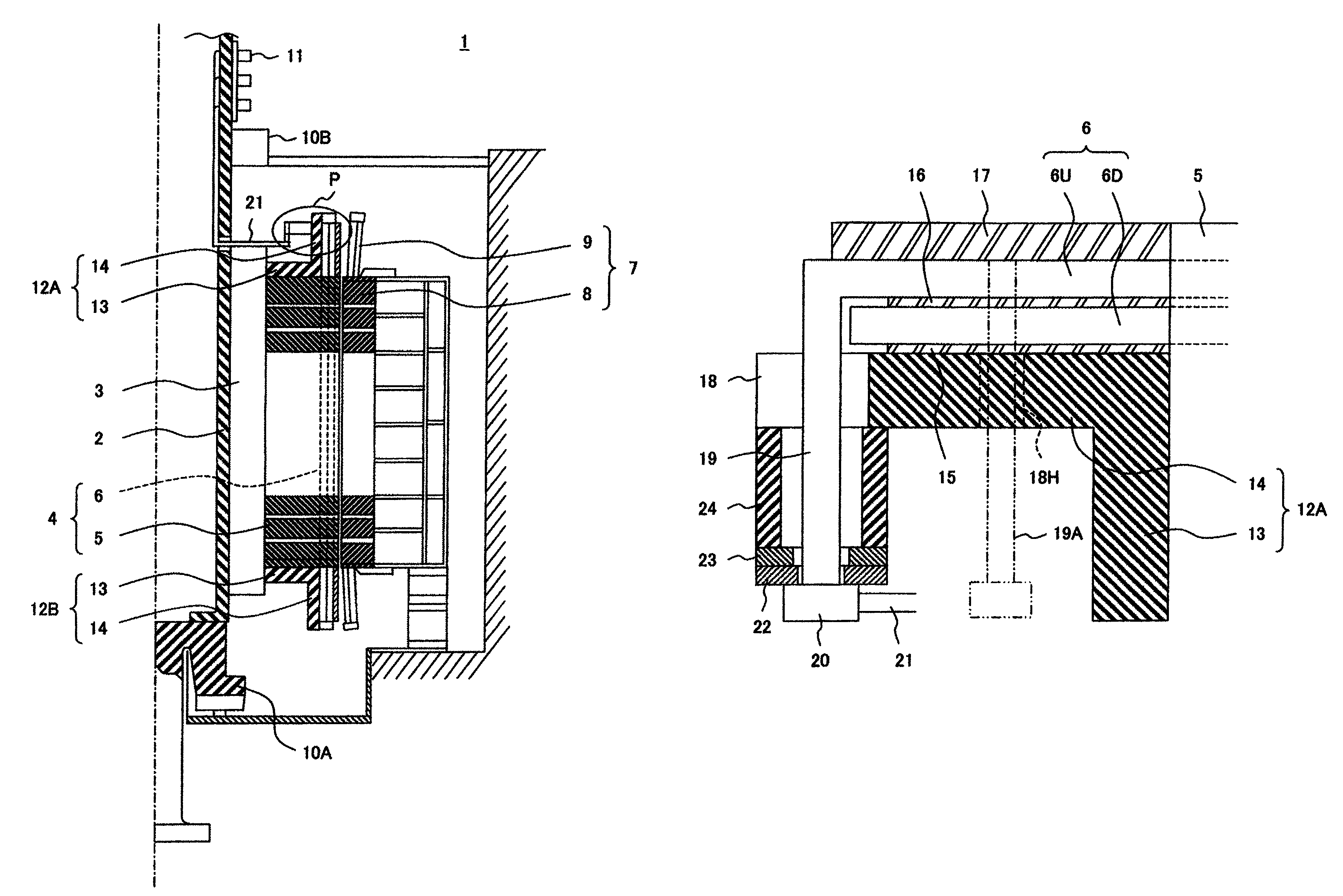
[0014]Hereinafter, an electric rotating machine according to the present invention will be described based on a generator motor shown in FIG. 1 and FIG. 2.

[0015]As shown in FIG. 1, a generator motor 1 generally includes: a rotor 4 fixed to a rotary shaft 2 via a spider arm 3; a stator 7 that faces the rotor 4 via a gap in the diameter direction; a first bearing 10A and a second bearing 10B that rotatably support the rotary shaft 2; and a slip ring 11 provided in the vicinity of a top end of the rotary shaft 2. A pump turbine is connected to a rotating portion below the first bearing 10A, although the illustration is omitted.

[0016]The rotor 4 includes: a rotor core 5 stacked in the direction of the rotary shaft; and a rotor winding 6 incorporated in a plurality of winding grooves (not shown) that are long in the axis direction, the winding grooves being formed in the diameter direction on the outer circumferential side of the rotor core 5, wherein the rotor core 5 is pressurized in t...

second embodiment

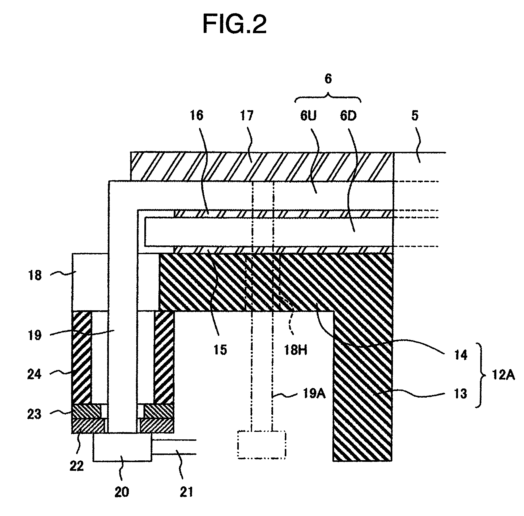
[0028]FIG. 4 shows the electric rotating machine according to the present invention. The duplicated detailed description will be omitted since the same reference numeral as that of FIG. 1 to FIG. 3 represents an identical component member.

[0029]In the second embodiment, a configuration different from the first embodiment lies in that the lead conductor 19 composed of a solid lead conductor 19A and a flexible lead conductors 19B.

[0030]Specifically, the side connected to the upper rotor winding 6U is the solid lead conductor 19A, and the side connected to the stopper 20 is the flexible lead conductor 19B having a plurality of thin steel sheets stacked, for example.

[0031]By connecting the flexible lead conductor 19B to a part of the lead conductor 19 in this manner, the flexible lead conductor 19B can, when the rotor winding 6 generates heat and elongates during operation of the generator motor, deform and absorb the elongation, and therefore an excessive stress will not act on the con...


PUM


Abstract

A lead conductor penetrating portion that bring out lead conductors to the inner diameter side is formed in a winding holding portion of a clamp ring for holding a rotor winding that overhangs from a rotor core, and furthermore a stopper is formed in a lead portion on the inner diameter side of the lead conductor, and a centrifugal force-resistant member for holding a centrifugal force acting on the lead conductor is interposed between the stopper and the inner diameter side of the winding holding portion.

Description

BACKGROUND OF THE INVENTION[0001]The present invention relates to an electric rotating machine, such as a generator motor, which is directly connected to a pump turbine used in a pumped storage power plant, and in particular relates to an electric rotating machine wherein a lead conductor is brought out from a rotor winding to deliver / receive electric power to / from a fixed side.[0002]For example, in the electric rotating machine, such as a generator motor, a lead conductor of a rotor winding is brought out from an end of the rotor winding that overhangs from a rotor core, and is then led to an inner diameter, and is wired to a predetermined portion.SUMMARY OF THE INVENTION[0003]According to the structure of the conventional lead conductor described above, during operation of the electric rotating machine an excessive centrifugal force often acts on the lead conductor from the end of the rotor winding and displaces the whole lead conductor in the outer diameter direction. As a result...

Claims


Application Information

Patent Timeline
Patent Type & Authority Patents(United States)
IPC IPC(8): H02K3/51
CPCH02K3/51H02K2203/06
Inventor YANAGISAWA, YUKIYOSHIKUWAHARA, TAKESHI
Owner HITACHI MITSUBISHI HYDRO
Why Eureka
Try Eureka